| Designation | GOST 28984-91 |
| Title in Russian | Modular dimension coordination in construction. Key points |
| Title in English | Modular size coordination in building engineering. Basic rules |
| Date of entry into force | 01.07.1991 |
| OKS | 91.010.30 |
| KGS code | J02 |
| OKSTU code | 5002 |
| SRSTI rubricator index | 670105 |
| Keywords | provisions; dimensions ; |
| Type of standard | Fundamental Standards |
| Normative references to: GOST | GOST21778-81; GOST 21779-82; GOST 21780-83; GOST 26607-85 |
| The document was submitted by the CIS organization | Central Research Institute of Industrial Buildings of the State Construction Committee of the USSR |
| Department of Rostekhregulirovanie | 50 - Ministry of Construction of the Russian Federation |
| MND Developer | the Russian Federation |
| Date of last edition | 01.09.2004 |
| Number(s) of change(s) | reissue |
| Number of pages (original) | 11 |
| Organization - Developer | Central Research Institute of Industrial Buildings of the State Construction Committee of the USSR |
| Status | Active |
MODULAR SIZE COORDINATION
IN CONSTRUCTION
MAIN PROVISIONS
GOST 28984-91
USSR STATE CONSTRUCTION COMMITTEE
Moscow
STATE STANDARD OF THE UNION OF THE SSR
Introduction date 01.07.91
This standard applies to buildings and structures for various purposes in all sectors of the national economy.
The standard is mandatory for development:
norms, standards and other regulatory documents containing data on the regulation of sizes used for construction;
projects of buildings and structures;
assortments, nomenclatures, catalogs and projects of building structures and products;
assortments, nomenclatures, catalogs and projects of building equipment that replaces structural elements or forms a single whole with them (partition cabinets, built-in wardrobes, shelving in warehouses, etc.), as well as equipment, the dimensions of which elements individually and in combination with other elements or normalized free passages must be consistent with the dimensions of the space-planning and structural elements of buildings (elevators, escalators, bridge support, overhead and other cranes, sectional cabinets, kitchen equipment, tables for classrooms, etc.).
This standard is not mandatory for the design and construction of buildings and structures:
unique;
experimental, if such deviations are due to the peculiarities of the experiment;
with the use of products, the dimensions of which are not brought into line with the modular coordination of dimensions in construction, provided that the deviations do not lead to the need to change the established dimensions of other products;
with dimensions determined by specific types of equipment, the dimensions and shape of which prevent the application of the rules for modular coordination of dimensions in construction;
reconstructed, built earlier without observing the rules of modular coordination in construction (including those attached to objects) and restored;
designed in whole or in part with oblique and curvilinear outlines, and deviations in these cases are allowed only to the extent necessary in connection with the features of the form;
with the sizes established by special international agreements.
The standard establishes the main provisions of modular coordination of dimensions in the construction of buildings and structures, which is one of the foundations for the unification and standardization of dimensions in construction to ensure mutual consistency, interchangeability and limit the number of standard sizes of building products and equipment elements.
The special terms and explanations adopted in the standard are given in the appendix.
1.1. Modular dimension coordination in construction (MKRS) should be carried out on the basis of a modular spatial coordination system and provide for the preferential use of a rectangular modular spatial coordination system (Fig.).
When designing buildings, structures, their elements, building structures and products based on a modular spatial coordination system, horizontal and vertical modular grids are used on the corresponding planes of this system.
1.2. The ICRS establishes rules for assigning the following categories of sizes:
main coordination dimensions: steps ( L 0 , IN 0 ) and floor heights (H 0 ) buildings and structures;
element coordination dimensions: length (1 0 ), width ( b 0 ), heights ( h 0 ), thickness, diameter ( d 0 )
structural dimensions of elements: lengths (I) width (b), height ( h), thickness, diameter ( d).
2.1. To coordinate the dimensions, the main module was adopted, equal to 100 mm and designated by the letter M.
2.2. To assign the coordination dimensions of space-planning and structural elements, building products, equipment, as well as to build systematic series of homogeneous coordination dimensions, the following derived modules should be used along with the main one (Fig. ):
Rectangular Modular Spatial Coordination System
K 1, K 2, TO 3 - coefficients of multiplicity of modules in the plan and height of the building (structure)
Heck. one
enlarged modules (multimodules) 60M; 30M; 15 M ; 12M; 6M; 3M, respectively equal to 6000; 3000; 1500; 1200; 600; 300 mm;
fractional modules (submodules) 1/2 M; 15 M; 1/10 M; 1/20M; 1/50 M; 1/100M , respectively equal to 50; twenty; 10; five; 2; 1 mm.
The enlarged 15M module is allowed if it is necessary to supplement a number of sizes that are multiples of 30M and 60M, subject to feasibility studies.
The relationship between modules of different sizes
Heck. 2
2.3. Derived modules specified in paragraph., should be applied up to the following limiting coordination dimensions of the space-planning element, building structure, product or piece of equipment:
60M - in plan and in height without limitation;
30M - in terms of up to 18000 mm, with feasibility studies - without limitation; in height - without limitation;
15M - in terms of up to 18000 mm; in height - without limitation;
12M - in terms of up to 12000 mm; in height - without limitation;
6M - in terms of up to 7200 mm; in height - without limitation;
3M - in terms of up to 3600 mm, with feasibility studies in terms of up to 7200 mm, in height - without limitation;
M - for all measurements up to 1800 mm;
1 / 2 M - the same, up to 600 mm;
1/5 M - the same, up to 300 mm;
1 / 10 M - for all measurements within 150 mm;
1/20 M - the same, up to 100 mm;
1 / 50 M - the same, up to 50 mm;
1/100 M - the same, up to 20 mm.
The accepted limits for the use of modules are optional for additive (terms) coordination dimensions of structural elements.
It is allowed to use floor heights of 2800 mm, multiples of the module M, beyond the limit established for it.
2.4. Enlarged modules for dimensions in terms of each specific type of building, its planning and structural elements, openings, etc. must constitute a group selected from the general row established by paragraph, in such a way that each relatively larger module is a multiple of all smaller ones, which achieves compatibility of divisions of modular grids (damn).
In buildings consisting of separate interconnected buildings or relatively independent parts, different in terms of space-planning structure and structural system, each of the parts can use its own group of enlarged modules from those indicated in paragraph 1. .
3. COORDINATING AND STRUCTURAL DIMENSIONS OF BUILDING ELEMENTS AND EQUIPMENT ELEMENTS
3.1. The coordination dimensions of structural elements and equipment elements are taken equal to the corresponding dimensions of their coordination spaces.
3.2. The coordination dimensions of the structural elements are set depending on the main coordination dimensions of the building (structure).
3.3. The coordination size of a structural element is taken equal to the main coordination size of the building (structure), if the distance between the two coordination axes of the building (structure) is completely filled with this element (Fig.).
An example of a grouping of enlarged modules, ensuring the compatibility of modular grids
Heck. 3
Heck. 4
Note. Instead of the coordination dimensions indicated on the drawing L 0 , l 0 (length) can be appropriately taken B 0 , b 0 (width) or H 0, h 0 (height).
3.4. The coordination size of a structural element is taken equal to a part of the main coordination size of the building (structure), if several structural elements fill the distance between the two coordination axes of the building (structure) (Fig. a, b).
Heck. five
Note. On the drawings L 0 i , And l 0 i (where i = 1, 2, 3) have for L 0 , l 0 .
3.5. The coordination size of a structural element may be greater than the main coordination size of the building (structure) if the structural element goes beyond the main coordination size of the building (structure) (Fig.).
In this case
l 01 = L 01 + a 1 + a 2 ; (1)
l 02 = L 02 -a 2 . (2)
Heck. 6
3.6. The coordination dimensions of the openings of windows, doors and gates, the additive dimensions of structural elements in plan and height, as well as the dimensions of steps and floor heights in some buildings that do not require large space-planning elements, are preferably assigned multiples of the enlarged modules 12M, 6M and ZM.
3.7. Coordination dimensions that do not depend on the main coordination dimensions (for example, sections of columns, beams, wall and floor slab thicknesses) are preferably assigned as multiples of the main module M or fractional modules 1/2 M, 1/5 M.
3.8. The coordination thicknesses of plate products and thin-walled elements are assigned as multiples of fractional modules 1/10 M, 1/20 M , and the width of the seams and gaps between the elements is also a multiple of 1/50 M and 1/100 M.
Heck. 7
3.9. Coordination dimensions, multiples of 3M/2 and 1/2 M/2, are allowed when dividing in half coordination dimensions equal to an odd number of modules 3M and 1/2 M.
3.10. Structural dimensions (l , b , h , d ) building elements should be determined based on their coordination dimensions minus the corresponding parts of the gap width (Fig. ), i.e
l = l 0 - q 1 - q 2 . (3)
The dimensions of the gaps should be set in accordance with GOST 21778, GOST 21779, GOST 21780, GOST 26607.
4. LINKING THE STRUCTURAL ELEMENTS TO THE COORDINATION AXES
4.1. The location and relationship of structural elements should be coordinated on the basis of a modular spatial coordination system by linking them to the coordination axes.
4.2. The modular spatial coordination system and the corresponding modular grids with divisions that are multiples of a certain enlarged module should, as a rule, be continuous for the entire building or structure being designed (Fig. but).
A discontinuous modular spatial coordination system with paired coordination axes and inserts between them having the size b, c), it is allowed to apply for buildings with load-bearing walls in the following cases:
1) in places where expansion joints are installed;
2) with a thickness of internal walls of 300 mm or more, especially if they have ventilation ducts; in this case, the paired coordination axes pass within the thickness of the wall in such a way as to provide the necessary support area for the unified modular floor elements (Fig. in);
3) when a discontinuous system of modular coordinates provides a more complete unification of the standard sizes of industrial products, for example, with panels of external and internal longitudinal walls inserted between the edges of transverse walls and ceilings.
4.3. The binding of structural elements is determined by the distance from the coordination axis to the coordination plane of the element or to the geometric axis of its section.
4.3.1. The binding of load-bearing walls and columns to the coordination axes is carried out according to the sections located at the level of the upper floor or cover resting on them.
4.3.2. The constructive plane (face) of the element, depending on the features of its adjunction to other elements, may be separated from the coordination plane by a specified size or coincide with it.
Location of coordination axes in terms of buildings with load-bearing walls
a - a continuous system with the combination of coordination axes with the axes of the bearing walls; b - discontinuous system with paired coordination axes and inserts between them, c - discontinuous system with paired coordination axes passing within the thickness of the walls
Heck. 8
4.4. The binding of structural elements of buildings to the coordination axes should be taken into account the use of building products of the same standard sizes for medium and extreme homogeneous elements, as well as for buildings with different structural systems.
4.5. The binding of load-bearing walls to the coordination axes is taken depending on their design and location in the building.
4.5.1. The geometric axis of the internal load-bearing walls must be aligned with the coordination axis (Fig. but); an asymmetric location of the wall with respect to the coordination axis is allowed in cases where it is advisable for the mass use of unified building products, for example, elements of stairs and ceilings.
4.5.2. The internal coordination plane of the external load-bearing walls should be displaced inside the building by a distance f from the coordination axis (Fig., c), equal to half the coordination size of the thickness of the parallel internal load-bearing wall d 0 in / 2 or multiple of M, 1/2 M or 1/5 M . When supporting floor slabs for the entire thickness of the bearing wall, it is allowed to align the outer coordination plane of the walls with the coordination axis (Fig. G).
4.5.3. With walls made of non-modular brick and stone, it is allowed to adjust the binding size in order to apply the standard sizes of floor slabs, elements of stairs, windows, doors and other elements used in other structural systems of buildings and installed in accordance with the modular system.
Attaching walls to coordinate axes
Heck. nine
Notes:
1. Anchor sizes are indicated from the coordination axes to the coordination planes of the elements.
2. The outer plane of the outer walls is on the left side of each image.
4.6. The internal coordination plane of external self-supporting and curtain walls must be aligned with the coordination axis (Fig. e) or shift by size e taking into account the binding of load-bearing structures in the plan and the features of the adjoining walls to vertical load-bearing structures or ceilings (Fig. e).
4.7. Binding of columns to coordination axes in frame buildings should be taken depending on their location in the building.
4.7.1. In frame buildings, the columns of the middle rows should be positioned so that the geometric axes of their section coincide with the coordination axes (Fig. but). Other column bindings are allowed; in places of expansion joints, height differences (p.) and at the ends of buildings, as well as in some cases, due to the unification of floor elements in buildings with different support structures.
4.7.2. The binding of the extreme rows of columns of frame buildings and the extreme coordination axes is taken taking into account the unification of the extreme structural elements (crossbars, wall panels, slabs, ceilings and coatings) with ordinary elements; at the same time, depending on the type and structural system of the building, the binding should be carried out in one of the following ways:
1) the internal coordination plane of the columns is shifted from the coordination axes into the building by a distance equal to half the coordination size of the width of the column of the middle rows b);
2) the geometric axis of the columns is combined with the coordination axis (Fig. in);
3) the outer coordination plane of the columns is combined with the coordination axis (Fig. G).
4.7.3. The outer coordination plane of the columns can be shifted outward from the coordination axes by a distance f(dev. e), a multiple of the 3M modulus and, if necessary, M or 1 / 2 M.
At the ends of buildings, it is allowed to shift the geometric axes of the columns inside the building by a distance e), a multiple of 3M and, if necessary, M or 1/2 M.
4.7.4. When binding the columns of the extreme rows to the coordination axes perpendicular to the direction of these rows, the geometric axes of the columns should be combined with the indicated coordination axes; exceptions are possible in relation to corner columns and columns at the ends of buildings and expansion joints.
4.8. In buildings in places of height difference and expansion joints carried out on paired or single columns (or load-bearing walls) tied to double or single coordination axes, the following rules should be followed:
1) distance from between paired coordination axes (Fig. a, b, c) must be a multiple of the 3M modulus and, if necessary, M or 1/2 M; the binding of each of the columns to the coordination axes must be taken in accordance with the requirements of clause;
2) with paired columns (or load-bearing walls) tied to a single coordination axis, the distance to from the coordination axis to the geometric axis of each of the columns (Fig. d) must be a multiple of 3M and, if necessary, M or 1/2 M;
3) with single columns tied to a single coordination axis, the geometric axis of the columns is combined with the coordination axis (Fig. e).
Note. When the wall is located between paired columns, one of its coordination planes coincides with the coordination plane of one of the columns.
Binding columns of frame buildings to coordination axes
Heck. 10
Notes:
1. The internal coordination planes of the walls (shown conditionally in the drawing) can move outward or inward, depending on the design features of the wall and its fastening
2. The dimensions of the bindings from the coordination axes are indicated to the coordination planes of the elements.
Binding of columns and walls to coordination axes in places of expansion joints
Heck. eleven
4.9. In volume-block buildings, volume blocks should, as a rule, be placed symmetrically between the coordination axes of a continuous modular grid.
4.10. In multi-storey buildings, the coordination planes of the finished floor of the landings should be combined with the horizontal main coordination planes (Fig. but).
4.11. In one-story buildings, the coordination plane of the finished floor should be aligned with the lower horizontal main coordination plane (Fig. b).
In one-story buildings with a sloping floor, the upper horizontal line of the floor intersection with the coordination plane of the outer walls should be aligned with the lower horizontal main coordination plane.
4.12. In one-story buildings, the lowest reference plane of the roof structure is combined with the upper horizontal main coordination plane (Fig. b).
4.13. The binding of the elements of the basement part of the walls to the lower horizontal main coordination plane of the first floor and the binding of the frieze part of the walls to the upper horizontal main coordination plane of the upper floor are taken in such a way that the coordination dimensions of the lower and upper wall elements are multiples of the 3M module and, if necessary, M or 1/2 M.
Modular (coordination) floor height
1 - coordination plane of the clean floor; 2 - false ceiling
Heck. 12
APPENDIX
Reference
TERMS AND EXPLANATIONS
|
Explanation |
|
|
1. Modular size coordination in construction (MKPC) |
Mutual coordination of the dimensions of buildings and structures, as well as the dimensions and location of their elements, building structures, products and equipment elements based on the use of modules |
|
Conventional linear unit of measurement. used to coordinate the dimensions of buildings and structures, their elements, building structures, products and equipment elements |
|
|
3. Main module |
A module taken as a basis for assigning other modules derived from it |
|
4. Derived module |
A module that is a multiple of the main module or that forms part of it |
|
5. Enlarged module (multimodule) |
Derived module that is a multiple of the main module |
|
6. Fractional module (submodule) |
Derived module that is part of the main module |
|
7. Modular spatial coordination system |
Conditional three-dimensional system of planes and lines of their intersection with distances between them equal to the main or derived modules |
|
8. Coordination plane |
One of the planes of the modular spatial coordination system, limiting the coordination space |
|
9. Main coordination plane |
One of the coordination planes that determine the division of buildings into space-planning elements |
|
10. Coordination line |
Intersection line of coordination planes |
|
11. Coordination space |
Modular space, limited by coordination planes, designed to accommodate a building, structure, their element, structure, product, piece of equipment |
|
12. Modular grid |
A set of lines on one of the planes of the modular spatial coordination system |
|
13. Coordination axis |
One of the coordination lines that define the division of a building or structure into modular steps and floor heights |
|
14. Binding to the coordinate axis |
Location of structural and building elements, as well as built-in equipment, in relation to the coordination axis |
|
15. Modular size |
Size equal to or multiple of the parent or derived module |
|
16. Coordinating size |
Modular size that defines the boundaries of the coordination space in one of the directions |
|
17. Basic coordination dimensions |
Modular step sizes and floor heights |
|
18. Modular pitch |
Distance between two coordinate axes in plan |
|
19. Modular floor height (coordinating floor height) |
Distance between horizontal coordination planes bounding a building floor |
|
20. Structural dimension |
The design size of a building structure, product, piece of equipment, determined in accordance with the rules of the MKRS |
|
21. Paste |
The space between two adjacent main coordination planes at the break points of the modular coordination system, including the places of expansion joints |
INFORMATION DATA
1. DEVELOPED AND INTRODUCED by the Central Research and Design and Experimental Institute industrial buildings and structures (TsNIIpromzdaniy) Gosstroy of the USSR
DEVELOPERS
Ya. P. Whatman, cand. tech. sciences (topic leader); M. R. Nikolaev; G. P. Volodin; M. I. Ivanov; L. S. Exler; D. M. Lakovsky; E. I. Pishchik; L. G. Movshovich
2. APPROVED AND INTRODUCED BY Decree of the State Construction Committee of the USSR dated April 10, 1991 No. 16
3. INTRODUCED FOR THE FIRST TIME
4. REFERENCE REGULATIONS AND TECHNICAL DOCUMENTS
|
Item number |
|
|
GOST 21778-81 |
|
|
GOST 21779-82 |
|
|
GOST 21780-83 |
|
|
GOST 26607-85 |
Download document
GOST 28984-91
INTERSTATE STANDARD
MODULAR COORDINATION
DIMENSIONS IN CONSTRUCTION
MAIN PROVISIONS
IPK STANDARDS PUBLISHING HOUSE
Moscow
INTERSTATE STANDARD
Date of introduction 01.07.91
This standard applies to buildings and structures for various purposes in all sectors of the national economy.
The standard is mandatory for development:
Norms, standards and other regulatory documents containing data on the regulation of sizes used for construction;
Projects of buildings and structures;
Assortments, nomenclatures, catalogs and projects of building structures and products;
Assortments, nomenclatures, catalogs and projects of building equipment that replaces structural elements or forms a single whole with them (partition cabinets, built-in wardrobes, shelving in warehouses, etc.), as well as equipment, the dimensions of which elements individually and in combination with other elements or normalized free passages must be consistent with the dimensions of the space-planning and structural elements of buildings (elevators, escalators, bridge support, overhead and other cranes, sectional cabinets, kitchen equipment, tables for classrooms, etc.).
Reconstructed, built earlier without observing the rules of modular coordination in construction (including those attached to objects) and restored;
Designed in whole or in part with oblique and curvilinear outlines, and deviations in these cases are allowed only to the extent necessary due to the peculiarities of the form;
With dimensions established by special international agreements.
The standard establishes the main provisions of modular coordination of dimensions in the construction of buildings and structures, which is one of the foundations for the unification and standardization of dimensions in construction to ensure mutual consistency, interchangeability and limit the number of standard sizes of building products and equipment elements.
The special terms and explanations adopted in the standard are given in the appendix.
1. GENERAL INSTRUCTIONS
1.1. Modular size coordination in construction (MKRS) should be carried out on the basis of a modular spatial coordination system and provide for the preferred use of a rectangular modular spatial coordination system (Fig. 1).
When designing buildings, structures, their elements, building structures and products based on a modular spatial coordination system, horizontal and vertical modular grids are used on the corresponding planes of this system.
1.2. MKRS establishes rules for assigning sizes to the following categories:
The main coordination sizes - steps ( L 0 , IN 0) and floor heights ( H 0) buildings and structures;
Coordination dimensions of elements - lengths ( l 0), width ( b 0), heights ( h 0), thickness, diameter ( d 0);
Structural dimensions of elements - lengths ( l), width ( b), heights ( h), thickness, diameter ( d).
2. MODULES AND THEIR LIMITS
2.1. To coordinate the dimensions, the main module was adopted, equal to 100 mm and designated by the letter M.


2.2. To assign the coordination dimensions of space-planning and structural elements, building products, equipment, as well as to build systematic series of homogeneous coordination dimensions, the following derived modules should be used along with the main one (Fig. 2):
Enlarged modules (multi-modules) 60M, 30M, 15M, 12M, 6M, 3M, respectively equal to 6000, 3000, 1500, 1200, 600, 300 mm;
Fractional modules (submodules) 1/2 M, 1/5 M, 1/10 M, 1/20 M, 1/50 M, 1/100 M, respectively equal to 50, 20, 10, 5, 2, 1 mm.
The enlarged module 15M is allowed if it is necessary to supplement a number of sizes, multiples of 30M and 60M, if there are feasibility studies.
6M - in terms of up to 7200 mm, in height - without limitation;
3M - in plan and in height up to 3600 mm, with feasibility studies in plan - up to 7200 mm, in height - without limitation;
M - for all measurements up to 1800 mm;
1/2 M - the same, up to 600 mm;
1/5 M - the same, up to 300 mm;
1 / 10 M - for all measurements within 150 mm;
1/20 M - the same, up to 100 mm;
1/50 M - the same, up to 50 mm;
1/10 0 M - the same, up to 20 mm.
The accepted limits for the use of modules are optional for additive (terms) coordination dimensions of structural elements.
It is allowed to use floor heights of 2800 mm, multiples of the module M, beyond the limit established for it.
2.4. Enlarged modules for dimensions in terms of each specific type of building, its planning and structural elements, openings, etc. must constitute a group selected from the general series established by clause 2.2, so that each relatively larger module is a multiple of everything smaller than the compatibility of divisions of modular grids is achieved (Fig. 3).
In buildings consisting of separate interconnected buildings or relatively independent parts, different in terms of space-planning structure and structural system, each of the parts can use its own group of enlarged modules from those indicated in clause 2.2.
3. COORDINATING AND STRUCTURAL DIMENSIONS OF BUILDING
ELEMENTS AND EQUIPMENT ELEMENTS
3.1. The coordination dimensions of structural elements and equipment elements are taken equal to the corresponding dimensions of their coordination spaces.
3.2. The coordination dimensions of the structural elements are set depending on the main coordination dimensions of the building (structure).
3.3. The coordination size of a structural element is taken equal to the main coordination size of the building (structure), if the distance between the two coordination axes of the building (structure) is completely filled with this element (Fig. 4).


Note. Instead of the coordination dimensions indicated on the drawing L 0 , l 0 (length) can be appropriately taken IN 0 , b 0 (width) or H 0 , h 0 (height).

3.4. The coordination size of a structural element is taken equal to the part of the main coordination size of the building (structure), if several structural elements fill the distance between the two coordination axes of the building (structure) (Fig. 5a, b).
Note. In drawings 5 and 6 L 0i And l 0 i(where i= 1, 2, 3) have the same meaning as in Sec. 1.2 for L0 And l 0 .
3.5. The coordination size of the structural element may be greater than the main coordination size of the building (structure) if the structural element goes beyond the main coordination size of the building (structure) (Fig. 6).
In this case
l 01 = L 01 + a 1 + but 2 , (1)
l 02 = L 02 - a 2 . (2)

3.6. The coordination dimensions of the openings of windows, doors and gates, the additive dimensions of structural elements in plan and height, as well as the dimensions of steps and floor heights in some buildings that do not require large space-planning elements, are preferably assigned multiples of the enlarged modules 12M, 6M and 3M.
3.7. Coordination dimensions that do not depend on the main coordination dimensions (for example, sections of columns, beams, wall and floor slab thicknesses) are preferably assigned as multiples of the main module M or fractional modules 1/2 M, 1/5 M.
3.8. The coordination thicknesses of plate products and thin-walled elements are assigned as multiples of fractional modules 1/10 M, 1/20 M, and the width of the seams and gaps between the elements is also a multiple of 1/50 M and 1/100 M.
3.9. Coordination dimensions, multiples of 3M/2 and 1/2 M/2, are allowed when dividing in half coordination dimensions equal to an odd number of modules 3M and 1/2 M.
3.10. Structural dimensions ( l, b, h, d) building elements should be determined based on their coordination dimensions minus the corresponding parts of the width of the gaps (Fig. 7), that is
l = l 0 - q 1 - q 2 . (3)

The dimensions of the gaps should be set in accordance with GOST 21778, GOST 21779, GOST 21780, GOST 26607.
4. LINKING THE STRUCTURAL ELEMENTS TO THE COORDINATION AXES
4.1. The location and relationship of structural elements should be coordinated on the basis of a modular spatial coordination system by linking them to the coordination axes.
4.2. The modular spatial coordination system and the corresponding modular grids with divisions that are multiples of a certain enlarged module should, as a rule, be continuous for the entire building or structure being designed (Fig. 8a).
A discontinuous modular spatial coordination system with paired coordination axes and inserts between them, having a size C, a multiple of the smaller module (Fig. 8b, c), is allowed to be used for buildings with load-bearing walls in the following cases:
1) in places where expansion joints are installed;
2) with a thickness of internal walls of 300 mm or more, especially if they have ventilation ducts; in this case, paired coordination axes pass within the thickness of the wall in such a way as to provide the necessary support area for unified modular floor elements (Fig. 8c);
3) when a discontinuous system of modular coordinates provides a more complete unification of the standard sizes of industrial products, for example, with panels of external and internal longitudinal walls inserted between the edges of transverse walls and ceilings.
4.3. The binding of structural elements is determined by the distance from the coordination axis to the coordination plane of the element or to the geometric axis of its section.

but- a continuous system with the combination of coordination axes with the axes of the bearing walls;
b- discontinuous system with paired coordination axes and inserts between them;
in- discontinuous system with paired coordination axes passing within the thickness of the walls
4.3.1. The binding of load-bearing walls and columns to the coordination axes is carried out according to the sections located at the level of the upper floor or cover resting on them.
4.3.2. The constructive plane (face) of the element, depending on the features of its adjunction to other elements, may be separated from the coordination plane by a specified size or coincide with it.
4.4. The binding of structural elements of buildings to the coordination axes should be taken into account the use of building products of the same standard sizes for medium and extreme homogeneous elements, as well as for buildings with different structural systems.
4.5. The binding of load-bearing walls to the coordination axes is taken depending on their design and location in the building.
4.5.1. The geometric axis of the internal load-bearing walls must be aligned with the coordination axis (Fig. 9a); an asymmetric arrangement of the wall with respect to the coordination axis is allowed in cases where it is advisable for the mass use of unified building products, for example, elements of stairs and ceilings.

Notes:
1. Anchor sizes are indicated from the coordination axes to the coordination planes of the elements.
2. The outer plane of the outer walls is on the left side of each image.
4.5.2. The internal coordination plane of the external load-bearing walls should be displaced inside the building by a distance f from the coordination axis (Fig. 9b, c), equal to half the coordination size of the thickness of the parallel internal load-bearing wall d 0 in /2 or a multiple of M, 1/2 M or 1/5 M. When supporting floor slabs for the entire thickness of the bearing wall, it is allowed to align the outer coordination plane of the walls with the coordination axis (Fig. 9d).
4.5.3. With walls made of non-modular brick and stone, it is allowed to adjust the binding size in order to apply the standard sizes of floor slabs, elements of stairs, windows, doors and other elements used in other structural systems of buildings and installed in accordance with the modular system.
4.6. The internal coordination plane of the external self-supporting and curtain walls must be aligned with the coordination axis (Fig. 9d) or shifted by a size e taking into account the binding of load-bearing structures in the plan and the features of the adjoining walls to vertical load-bearing structures or ceilings (Fig. 9e).
4.7. Binding of columns to coordination axes in frame buildings should be taken depending on their location in the building.
4.7.1. In frame buildings, the columns of the middle rows should be positioned so that the geometric axes of their section are aligned with the coordination axes (Fig. 10a). Other bindings of columns are allowed in places of expansion joints, height differences (clause 4.8) and at the ends of buildings, as well as in some cases, due to the unification of floor elements in buildings with supports of various designs.
4.7.2. The binding of the extreme rows of columns of frame buildings to the extreme coordination axes is taken taking into account the unification of the extreme structural elements (crossbars, wall panels, floor slabs and coatings) with ordinary elements; at the same time, depending on the type and structural system of the building, the binding should be carried out in one of the following ways:
1) the internal coordination plane of the columns is shifted from the coordination axes into the building by a distance equal to half the coordination size of the width of the column of the middle rows b 0 s /2 (Fig. 10b);
2) the geometric axis of the columns is combined with the coordination axis (Fig. 10c);
3) the outer coordination plane of the columns is combined with the coordination axis (Fig. 10d).
4.7.3. The outer coordination plane of the columns can be shifted outward from the coordination axes by a distance f(Fig. 10e), a multiple of the module 3M and, if necessary, M or 1 / 2 M.
At the ends of buildings, it is allowed to shift the geometric axes of the columns inside the building by a distance k(Fig. 10e), a multiple of the module 3M and, if necessary, M or 1 / 2 M.
4.7.4. When binding the columns of the extreme rows to the coordination axes perpendicular to the direction of these rows, the geometric axes of the columns should be combined with the indicated coordination axes; exceptions are possible in relation to corner columns and columns at the ends of buildings and expansion joints.
4.8. In buildings in places of height difference and expansion joints carried out on paired or single columns (or load-bearing walls) tied to double or single coordination axes, the following rules should be followed:
1) the distance c between the paired coordination axes (Fig. 11a, b, c) must be a multiple of the 3M module and, if necessary, M or 1/2 M; the binding of each of the columns to the coordination axes must be taken in accordance with the requirements of clause 4.7;

Notes:
1. The internal coordination planes of the walls (shown conditionally in the drawing) can move outward or inward, depending on the design features of the wall and its fastening.
2. The dimensions of the bindings from the coordination axes are indicated to the coordination planes of the elements.
2) with paired columns (or load-bearing walls) tied to a single coordination axis, the distance k from the coordination axis to the geometric axis of each of the columns (Fig. 11d) should be a multiple of the module 3M and, if necessary, M or 1/2 M;
3) with single columns tied to a single coordination axis, the geometric axis of the columns is combined with the coordination axis (Fig. 11e).
Note. When the wall is located between paired columns, one of its coordination planes coincides with the coordination plane of one of the columns.

4.9. In volume-block buildings, volume blocks should, as a rule, be placed symmetrically between the coordination axes of a continuous modular grid.
4.10. In multi-storey buildings, the coordination planes of the finished floor of the landings should be combined with the horizontal main coordination planes (Fig. 12a).

1 - coordination plane of the clean floor; 2 - false ceiling
4.11. In one-story buildings, the coordination plane of the finished floor should be combined with the lower horizontal main coordination plane (Fig. 12b).
In one-story buildings with a sloping floor, the upper horizontal line of the floor intersection with the coordination plane of the outer walls should be aligned with the lower horizontal main coordination plane.
4.12. In one-story buildings, the lowest reference plane of the roof structure is combined with the upper horizontal main coordination plane (Fig. 12b).
4.13. The binding of the elements of the basement part of the walls to the lower horizontal main coordination plane of the first floor and the binding of the frieze part of the walls to the upper horizontal main coordination plane of the upper floor are taken in such a way that the coordination dimensions of the lower and upper wall elements are multiples of the 3M module and, if necessary, M or 1/2 M.
APPENDIX
Reference
TERMS AND EXPLANATIONS
|
Explanation |
|
|
1. Modular dimension coordination in construction (MKRS) |
Mutual coordination of the dimensions of buildings and structures, as well as the dimensions and location of their elements, building structures, products and equipment elements based on the use of modules |
|
2. Module |
Conventional linear unit of measurement used to coordinate the dimensions of buildings and structures, their elements, building structures, products and equipment elements |
|
3. Main module |
A module taken as a basis for assigning other modules derived from it |
|
4. Derived module |
A module that is a multiple of the main module or that forms part of it |
|
5. Enlarged module (multimodule) |
Derived module that is a multiple of the main module |
|
6. Fractional module (submodule) |
Derived module that is part of the main module |
|
7. Modular spatial coordination system |
Conditional three-dimensional system of planes and lines of their intersection with distances between them equal to the main or derived modules |
|
8. Coordination plane |
One of the planes of the modular spatial coordination system, limiting the coordination space |
|
9. Main coordination plane |
One of the coordination planes that determine the division of buildings into space-planning elements |
|
10. Coordination line |
Intersection line of coordination planes |
|
11. Coordination space |
Modular space, limited by coordination planes, designed to accommodate a building, structure, their element, structure, product, piece of equipment |
|
12. Modular grid |
A set of lines on one of the planes of the modular spatial coordination system |
|
13. Coordination axis |
One of the coordination lines that define the division of a building or structure into modular steps and floor heights |
|
14. Binding to the coordinate axis |
Location of structural and building elements, as well as built-in equipment, in relation to the coordination axis |
|
15. Modular size |
Size equal to or multiple of the parent or derived module |
|
16. Coordinating size |
Modular size that defines the boundaries of the coordination space in one of the directions |
|
17. Basic coordination dimensions |
Modular step sizes and floor heights |
|
18. Modular pitch |
Distance between two coordinate axes in plan |
|
19. Modular floor height (coordinating floor height) |
Distance between horizontal coordination planes bounding a building floor |
|
20. Structural dimension |
The design size of a building structure, product, piece of equipment, determined in accordance with the rules of the MKRS |
|
21. Paste |
The space between two adjacent main coordination planes at breaks in the modular coordination system, including at expansion joints |
INFORMATION DATA
1. DEVELOPED AND INTRODUCED by the Central Research and Design and Experimental Institute of Industrial Buildings and Structures (TsNIIpromzdaniy) of the USSR State Construction Committee
2. APPROVED AND INTRODUCED BY Decree of the State Construction Committee of the USSR dated April 10, 1991 No. 16
3. INTRODUCED FOR THE FIRST TIME
4. REFERENCE REGULATIONS AND TECHNICAL DOCUMENTS
5. REPUBLICATION. September 2004
INTERSTATE COUNCIL FOR STANDARDIZATION, METROLOGY AND CERTIFICATION
(MGS)
INTERSTATE COUNCIL FOR STANDARDIZATION, METROLOGY AND CERTIFICATION
(ISC)
Foreword
The goals, basic principles and basic procedure for carrying out work on interstate standardization are established by GOST 1.0-92 “Interstate standardization system. Basic Provisions” and GOST 1.2-2009 “Interstate Standardization System. Interstate standards, rules and recommendations for interstate standardization. Rules for the development, adoption, application, updating and cancellation "
About the standard
1 DESIGNED BY OPEN joint stock company"Central Research and Design and Experimental Institute of Industrial Buildings and Structures" (OJSC "TsNIIPromzdaniy")
2 INTRODUCED by the Technical Committee for Standardization TC 465 "Construction"
3 ADOPTED by the Interstate Scientific and Technical Commission for Standardization, Technical Regulation and Conformity Assessment in Construction (MNTKS) (Supplement No. 1 to Annex D of Protocol No. 39 dated December 8, 2011)
| Short title | Code of the country | Abbreviated name of the body |
| Azerbaijan | Ministry of Urban Development |
|
| State Committee for Urban Planning and Architecture |
||
| Kyrgyzstan | Gosstroy |
|
| Ministry of Construction and Territorial Development |
||
| Department for Regulation of Urban Planning Activities of the Ministry of Regional Development |
||
| Tajikistan | Agency for Construction and Architecture under the Government |
|
| Uzbekistan | Gosarchitektstroy |
4 This standard complies with the following international standards:
ISO 1006 Building construction - Modular coordination - Basic module
ISO 2848:1984 Building construction - Modular coordination - Principles and rules.
Degree of conformity - non-equivalent (NEQ)
5 Order federal agency on technical regulation and metrology dated May 24, 2012 No. 77-st interstate standard GOST 28984-2011 was put into effect as a national standard Russian Federation since January 1, 2013
Information on the entry into force (termination) of this standard and amendments to it is published in the index "National Standards".
Information about changes to this standard is published in the index (catalog) "National Standards", and the text of the changes - in information signs "National standards". In case of revision or cancellation of this standard, the relevant information will be published in the information index "National Standards"
GOST 28984-2011
INTERSTATE STANDARD
MODULAR COORDINATION OF DIMENSIONS IN CONSTRUCTION
MAIN PROVISIONS
Modular coordination of construction dimensions. General
Introduction date - 2013-01-01
1 area of use
This standard applies to buildings and structures of various functional purpose.
This standard establishes the basic provisions of modular size coordination in the design and construction of buildings and structures, which is the basis for unification and standardization, ensuring mutual consistency and interchangeability of building products, equipment elements and other products used in the construction process and subsequent operation.
This standard does not apply to the design and construction of buildings and structures:
With dimensions determined by specific types of equipment, the dimensions and shape of which prevent the application of the rules for modular coordination of dimensions in construction;
Subject to reconstruction, built earlier without observing the rules for modular coordination of sizes in construction (including those attached to objects);
Designed in whole or in part with oblique and curvilinear outlines.
This standard uses common international terms, common meanings for the most commonly used enlarged modules (“multi-modules”) and fractional modules (“sub-modules”).
GOST 21778-81 System for ensuring the accuracy of geometric parameters in construction. Key points
GOST 21779-82 System for ensuring the accuracy of geometric parameters in construction. Technological approvals
GOST 21780-2006 Interstate standard. System for ensuring the accuracy of geometric parameters in construction. Accuracy calculation
GOST 26607-85 System for ensuring the accuracy of geometric parameters in construction. functional tolerances
Note - When using this standard, it is advisable to check the validity of the reference standards according to the "National Standards" index, compiled as of January 1 of the current year, and according to the corresponding information indexes published in the current year. If the reference standard is replaced (modified), then when using this standard, you should be guided by the replacing (modified) standard. If the referenced standard is canceled without replacement, the provision in which the reference to it is given applies to the extent that this reference is not affected.
3 Terms and definitions
In this standard, the following terms are used with their respective definitions:
3.1 module (main module): The initial linear conventional unit of measurement used for mutual consistency and coordination of the sizes of buildings and structures, their elements, building structures, products and equipment elements. The main module is taken as the basis for assigning other modules derived from it. The international standardized designation of the main module is "M".
3.2 enlarged module (multimodule): A derived value that is a multiple of the base modulus. The enlarged module is used to reduce the number of horizontal and vertical module sizes. The enlarged module is used as a basis (basis) for choosing enlarged dimensions when designing spaces and structural elements of buildings and structures.
3.3 fractional module (submodule): A derived quantity that is part of the main module.
3.4 modular size: Size equal to or a multiple of the main module, enlarged module (multimodule), or fractional module (submodule).
3.5 modular coordination spatial system: A conditional three-dimensional system of planes and lines of their intersection with distances between them equal to or multiples of the main module or multimodule.
3.6 modular coordination of dimensions in construction; MKRS: Mutual coordination of the sizes of buildings and structures, as well as the size and location of their elements, building structures, products and elements based on the use of modules.
3.7 coordination plane: One of the planes of the modular spatial coordination system that bounds the coordination space.
3.8 construction plane: The face of an element that limits its constructive dimension.
3.9 modular grid: A set of lines on one of the planes of a modular spatial coordination system. The main modular grid is a grid, the distance between the parallel lines of which is equal to the enlarged modules (multi-modules).
3.10 coordination line: The line of intersection of the coordination planes.
3.11 coordination space: Modular space, limited by coordination planes, designed to accommodate a building, structure, their elements, structures, products, equipment elements.
3.12 coordination axis: One of the coordination lines that define the division of a building or structure into modular steps and floor heights.
3.13 binding to the coordination axis: The location of space-planning structures and structural elements, as well as built-in equipment in relation to the coordination axis.
3.14 coordination size, main coordination sizes: Modular horizontal and/or vertical dimensions that define the boundaries of the coordination space in one of the directions. Geometric modular dimensions of spans, steps and floor heights.
3.15 modular step: The distance between two coordinate axes in the plan.
3.16 modular height floors (coordination height floors): The distance between the horizontal coordination planes bounding the floor of a building or structure.
3.17 room height from floor to ceiling: The design dimension is from the level of the finished floor to the bottom of the ceiling, including the suspended one.
3.18 height from the false ceiling to the bottom of the ceiling: Design dimension from the bottom of the false ceiling to the bottom of the ceiling and/or roof structure.
3.19 finished floor height: The design dimension is from the level of the top of the supporting structure to the mark of the level of the finished floor.
3.20 constructive size: The design size of a building structure, product, piece of equipment.
3.21 height difference: Design vertical dimension between two adjacent floors or roofs.
3.22 insert (non-modular size, neutral zone): The space between the coordination planes at the break points of the modular coordination system, including at the places of expansion, temperature or sedimentary joints, junctions of various modular grids, changes in the direction of modular grids (angle of rotation). Depending on the configuration of the insert, its dimensions can be accepted as non-modular.
4.1 Modular coordination of dimensions in construction is carried out on the basis of a modular spatial coordination system.
4.2 The MCRS provides for the preferred use of a rectangular modular spatial coordination system (see Figure 1).
4.3 The basics of modular coordination of dimensions in construction are:
Module (main module);
Enlarged modules (multimodules);
Fractional modules (submodules);
The coordinate system of the spatial coordination system, the use of horizontal and vertical modular grids.

to 1 M, to 2 M, to 3 M - coordination dimensions, multiples of the modulus
Figure 1 - Rectangular modular coordination system
4.4 When designing buildings, structures, their elements, building structures and products, it is allowed to use horizontal and vertical modular grids on the corresponding planes of the coordination system.
4.5 When assigning the dimensions and arrangement of elements, it is necessary, along with the functional and economic feasibility of the decisions made, to ensure that the number of standard sizes of building products is limited.
4.6 The largest dimensions of multimodules and submodules should be used.
4.7 MKRS establishes rules for assigning the following categories of sizes:
Main horizontal and vertical coordination dimensions in plan L 0 (span), IN 0 (step) and H 0 (floor height);
The focal dimensions of the elements (see Figure 6): lengths l 0 , width b 0 and height h 0 ;
Structural dimensions of elements (see figure 9): lengths l, width b and height h.
4.8 The use of modular dimensional coordination in construction is not meant to limit the use of products that do not conform to this standard.
5 Modules and rules for their use
5.1 Module (main module). The value of the main module for coordinating dimensions is taken equal to 100 mm and denoted by the letter "M".
5.2 To assign the coordination dimensions of space-planning and structural elements, building products, equipment, as well as to build systematic series of homogeneous coordination dimensions, derivative modules can be used along with the main one.
5.2.1 An enlarged module (multimodule) is recommended to be used when assigning coordination dimensions and dimensions of modular grids. It is possible to use the following multimodules: 60M; 30M; 15M; 12M; 6M; 3M equal to 6000; 3000; 1500; 1200; 600; 300 mm respectively.
5.2.2 The fractional module (submodule) can be used where it is impossible to apply the main module, when assigning dimensions smaller than the main module. It is possible to assign the following submodules: 1/2M; 1/4M; 1/5M, equal to 50, 25, 20 mm, respectively.
5.3 In buildings and structures, interconnections between various enlarged modules (multi-modules) should be provided.
5.4 The main modular grid is a grid, the distance between the parallel lines of which is equal to the enlarged modules (multi-modules).
5.5 Multi-module grids are grids used in addition to the main modular grid, in which the distances in two directions can be equal to different enlarged modules (multi-modules), see Figure 2.

Figure 2 - Multimodular grids
5.6 The modular spatial coordination system and the corresponding modular grids with divisions that are multiples of a certain multimodule should, as a rule, be continuous (see Figure 3a) for the entire building or structure being designed.
5.7 A discontinuous modular spatial coordination system with paired coordination axes (boundary binding) and non-modular dimensions (inserts) between them, with a size c that is a multiple of the smaller module (see Figures 3b, 3c), should be used:
In places where expansion and sedimentary joints are installed;
With a thickness of internal walls of 300 mm or more, including the presence of ventilation ducts in them;
If necessary, provide the angle of rotation of the spatial coordination system or modular grid (see Figure 4).
5.8 It is allowed to interrupt the modular grid if necessary to accommodate a non-modular element, for example, to accommodate a separating element in the form of a fire barrier. The width of the modular grid break zone (insert) can be modular or non-modular (see Figure 5).

Notes
a) Continuous system with the combination of coordination axes with the axes of the bearing walls;
b) Discontinuous system with paired coordination axes and inserts (neutral zones) between them;
c) Discontinuous system with paired coordination axes passing through the thickness of the walls
L 0 (l 0) - coordination size
Figure 3 - The location of the coordination axes in terms of buildings with load-bearing walls

Figure 4 - Angle of rotation of the spatial coordination system and / or modular grid

Figure 5 - Interruption of modular grids
5.9 Enlarged modules for the dimensions in terms of each specific type of buildings and structures, their planning and structural elements, openings, etc., are preferably assigned based on the condition that each relatively smaller module is a multiple of everything greater than the compatibility of divisions of modular grids is achieved.
5.9.1 Complete groups complying with this rule must be:
a) M-3M-6M-12M-60M;
b) M-3M-15M-30M-60M.
5.9.2 Incomplete groups, including those connected by a regular sequence of doubling modules, must be:
a) 3M-6M-12M - preferably for buildings and structures with a relatively equal size of the premises;
b) 15M-30M-60M - preferably for buildings and structures with relatively equal, but large room sizes, also applicable to other buildings with structural systems that allow considerable freedom in planning.
5.10 To reduce the number of standard sizes of building products, it is recommended to use larger modules, taking into account functional requirements and economic feasibility, as well as to select a limited number of preferred sizes that are multiples of these modules; the selection of sizes should be carried out by sequentially increasing their gradation or selectively.
5.11 Modular steps in frame buildings for various purposes and the corresponding lengths of slabs, beams, trusses, it is recommended to preferably take multiples of the largest of the installed enlarged modules (multi-modules) 60M and 30M, and for some types of buildings also 12M and 15M.
5.12 Multimodules 3M, 6M are preferably intended for dividing structural elements for the dimensions of openings and piers of external walls, placement of partitions, as well as for the dimensions of steps in some types of buildings with structural systems that limit the freedom of planning.
5.13 The main module M and the submodule 1/2M should be used as preferred for setting the coordination dimensions of the section of structural elements - columns, beams, wall thicknesses and floor slabs, dividing the planes of facades and interiors, for the coordination dimensions of facing tiles and other finishing products, as well as equipment elements. The same modules can be used for the dimensions of additional elements, openings, as well as for the dimensions and placement of partitions.
5.14 For arranging and sizing non-load-bearing partitions and openings of internal doors, as well as the coordination dimensions of additional, extreme and some other elements (for example, sections of columns and crane beams), if this is economically justified and does not lead to deviations from the modular dimensions of the elements adjacent to them for other purposes, the main module M and the submodule 1/2M are used.
5.15 Submodule 1/5M should be used for relatively small thicknesses of walls, partitions, floor slabs and coatings.
5.16 The accepted limits for the use of modules are optional for the terms (additive) of the coordination dimensions of structural elements, including for connections with separating elements or intervals.
6 Coordination and design dimensions of building elements and equipment elements
6.1 Coordination dimensions l 0 , b 0 , h 0 building structures, products, equipment elements are taken equal to the corresponding dimensions of their coordination spaces.
6.2 The coordination dimensions of the structural elements are set depending on the main coordination dimensions of the building and structure.
6.3 The coordination size of a structural element is taken equal to the main coordination size of the building and structure, if the distance between the two coordination axes of the building and structure is completely filled with this element (see Figure 6).

Note - Instead of the coordination dimensions of the length indicated in the figure ( L 0 (l 0) can be respectively taken width ( IN 0 (b 0) or height ( H 0 (h 0).
Figure 6 - Coordination element size
6.4 The choice of the limiting coordination dimensions of a building structure, product or piece of equipment in terms of and in height for derived modules should be based on their size and the possibility of maximum enlargement within the coordination size.
6.5 The terms (additive) dimensions of structural elements in plan and height, as well as the dimensions of spans, steps and floor heights that do not require large space-planning elements, are preferably assigned to multiples of multimodules 3M, 6M, 12M.
6.6 Modular (coordination) floor heights in all buildings, as well as the corresponding vertical coordination dimensions for columns, wall panels, large openings and gates, are assigned in accordance with multimodules 3M, 6M, with the exception of small openings, windows, doors, multiples of M.
6.7 Room height from finished floor to ceiling H h should be taken in accordance with the rules for assigning a modular floor height (see Figure 7).
6.8 Minimum height from the bottom of the false ceiling to the bottom of the ceiling H pp subject to placement in it engineering communications and equipment should be taken by 3M; to assign a size larger than this multi-module, the main module M should be used (see figure 7).
6.9 To ensure the coordination height when changing the level of floors or roofs (height difference H to /N n) from 300 to 2400 mm, use the 3M multi-module, over 2400 mm - the 6M multi-module (see Figure 8).
6.10 Coordination dimensions that do not depend on the main coordination dimensions (for example, sections of columns, beams, wall and ceiling thicknesses) are preferably assigned as multiples of the main module M or submodules 1/2M, 1/5M.
6.11 Structural dimensions l, b, h, d building elements should be determined based on their coordination dimensions minus the corresponding parts of the gap width (see Figure 9):
l = l 0 - q 1 - q 2 .
The dimensions of the gaps should be set in accordance with GOST 21778, GOST 21779, GOST 21780, GOST 26607.

1 - overlap; 2 - clean floor; 3 - false ceiling; d p - floor thickness
Figure 7 - Appointment of the coordination height of the floor, the height of the room and the minimum
height from the bottom of the suspended ceiling to the bottom of the ceiling

UCHP - clean floor level
Figure 8 - Changing the level of floors or roofs (height difference)

Figure 9 - Assignment of structural dimensions
7 Binding of structural elements to coordination axes
7.1 The location and interconnection of structural elements should be carried out on the basis of a modular spatial coordination system by linking them to the coordination axes.
7.2 The binding of structural elements is determined by the distance from the coordination axis to the coordination plane of the element or the geometric axis of its section.
7.3 The structural plane (face) of the element, depending on the features of its adjoining to other elements, may be separated from the coordination plane by a specified size or coincide with it.
7.4 The binding of structural elements of buildings and structures to the coordination axes should be taken into account the use of building products of the same size for middle and extreme homogeneous elements, as well as for buildings and structures with different structural systems.
7.5 The binding of load-bearing walls to the coordination axes is taken depending on their design and location in the building.
7.5.1 The geometric axis of the internal bearing walls, as a rule, should be aligned with the coordination axis (see Figure 10a).
7.5.2 The internal coordination plane of the external load-bearing walls should be displaced inside the building by a distance a from the coordination axis (see Figures 10b, 10c), equal to half the coordination size of the thickness of the parallel internal load-bearing wall d 0/2 or a multiple of M, 1/2M or 1/5M. When supporting floor slabs for the entire thickness of the bearing wall, it is allowed to align the outer coordination plane of the walls with the coordination axis (see Figure 10d).
7.5.3 For walls made of non-modular materials, it is allowed to adjust the binding size in order to apply the standard sizes of floor slabs, elements of stairs, windows, doors and other elements used in other structural systems of buildings and structures and installed in accordance with the modular system.

Notes
1 Snapping values from the coordination axes are specified to the coordination planes of the elements.
2 The outer plane of the outer walls is on the left side of each image.
Figure 10 - Binding of walls to coordination axes
7.6 The internal coordination plane of external self-supporting and curtain walls should be aligned with the coordination axis (see Figure 10d) or shifted by dimension e, taking into account the binding of load-bearing structures in the plan and the features of the adjoining walls to vertical load-bearing structures or ceilings (see Figure 10f).
7.7 The binding of columns in frame buildings should be taken depending on their location in the building.
7.7.1 In frame buildings, the columns of the middle rows should be located so that the geometric axes of their section are aligned with the coordination axes (see Figure 11a). Other bindings of columns are allowed in places of expansion joints, inserts (neutral zones), height differences and at the ends of buildings, as well as in some cases due to the unification of floor elements in buildings with different support structures.
7.7.2 Binding of the extreme rows of columns of frame buildings to the extreme coordination axes is accepted taking into account the unification of the extreme structural elements (crossbars, wall panels, floor slabs and coatings) with ordinary elements, while depending on the type and structural system of the building, the binding should be carried out by one of the following ways:
The geometric axis of the columns is combined with the coordination axis (see Figure 11b);
The outer coordination plane of the columns is aligned with the coordination axis (see Figure 11c).
7.7.3 At the ends of buildings, it is allowed to shift the geometric axes of the columns inside the building by a distance to(see Figure 11d), a multiple of 3M and, if necessary, M or 1/2M.
7.7.4 When binding the columns of the extreme rows to the coordination axes perpendicular to the direction of these rows, the geometric axes of the columns should be combined with the indicated coordination axes; exceptions are possible for corner columns and columns at the ends of buildings, expansion joints and inserts (see Figure 11e).
|
|
|
|
|
|


Figure 11 - Linking the columns of frame buildings to the coordination axes
7.8 In buildings, in places of height difference, expansion joints and inserts carried out on paired or single columns (or load-bearing walls) tied to double or single coordination axes, the following rules should be followed:
The distance c between the paired coordination axes (see figures 12a, 12b, 12c) must be a multiple of the 3M modulus and, if necessary, M or 1/2M; the binding of each of the columns to the coordination axes must be taken in accordance with the requirements of 7.7;
With paired columns (or load-bearing walls) tied to a single coordination axis, the distance f from the coordination axis to the geometric axis of each of the columns (see Figure 12d) must be a multiple of the module 3M and, if necessary, M or 1/2M;
With single columns tied to a single coordination axis, the geometric axis of the columns is aligned with the coordination axis (see Figure 12e).
Note - When the walls are located between paired columns, one of its coordination planes coincides with the coordination plane of one of the columns.
7.9 In buildings from three-dimensional blocks, as a rule, blocks should be placed symmetrically between the coordination axes of a continuous modular grid.
7.10 In multi-storey buildings, the coordination planes of the finished floor of the stairwells should be aligned with the horizontal main coordination planes (see Figure 13).
7.11 In one-story buildings, the coordination plane of the finished floor should be aligned with the lower horizontal main coordination plane (see Figure 14).
7.12 In one-story buildings, the lowest supporting part of the coating should be combined with the upper horizontal main coordination plane (see Figure 14).
7.13 The binding of the elements of the basement part of the walls to the lower horizontal main coordination plane of the first floor and the binding of the frieze part of the walls to the upper horizontal main coordination plane of the upper floor are taken in such a way that the coordination dimensions of the lower and upper wall elements are multiples of the module 3M and, if necessary, M or 1/2M.

Figure 12 - Binding of columns and walls to the coordination axes in the places of expansion joints

1
Figure 13 - Modular (coordination) floor height multi-storey buildings

1 - coordination plane of the clean floor
Figure 14 - Modular (coordination) floor height of one-story buildings
Annex A
(reference)
Table of the main indicators of modular size coordination in construction
Table A.1
| Name of indicator | Indicators of modular coordination (indicator, dimension) |
||||
| Russia (MKRS) | Germany (DIN) | USA (ASTM) | England (BS) |
||
| The main module | M = 100 mm (SI); | ||||
| Enlarged modules (multi-modules) | |||||
| Fractional modules (submodules) | |||||
| Modular spatial grids | |||||
| Multimodular grids | |||||
| Non-modular dimensions | Allowed | Allowed | Allowed, neutral zones | Allowed |
|
| Coordination dimensions | Multiple, non-modular sizes are allowed |
||||
| Main regulatory documents | This standard | ASTM E577-85(2002) | |||
Bibliography
| Construction. Modular coordination. The main module |
||
| (Building construction - Modular coordination - Basic module) |
||
| ISO 2848:1984 | Construction. Modular coordination. Principles and rules |
|
| (Building construction - Modular coordination - Principles and rules) |
||
| Construction. Modular coordination. Multimodules for horizontal coordination dimensions |
||
| (Building construction - Modular coordination - Multimodules for horizontal coordinating dimensions) |
||
| Construction. Modular coordination. Height of floors and rooms |
||
| (Building construction - Modular coordination - Storey heights and room heights) |
||
| Construction. Modular coordination. Series of preferred multi-modules for horizontal dimensions |
||
| (Building construction - Modular coordination - Series of preferred multimodular sizes for horizontal dimensions) |
||
| Construction. Modular coordination. Preferred Submodules |
||
| (Building construction - Modular coordination - Sub-modular increments) |
||
| British standard. Modular coordination requirements in construction |
||
| (British Standard Specification for Modular coordination in building) |
||
| ASTM E 577-85 | Modular coordination of elements and systems in construction (approved in 2002) |
|
| (ASTM E 577-85) | [(Reapproved 2002). Standard Guide for Dimensional Coordination of Rectilinear Building Parts ell IU OyolollloJ |
|
| Modular coordination in construction. (Approved: 2003-04-01) |
||
| (ONORM DIN 18000) | [(Ausgabe: 2003-04-01). Modulordnung im Bauwesen (Modular coordination in building)] |
Key words: modular coordination of dimensions in construction, module, enlarged module (multimodule), fractional module (submodule), coordination plane, coordination dimension, binding, constructive dimension, insert, modular grid, height difference, floor height, sizing, harmonization
INTERSTATE COUNCIL FOR STANDARDIZATION, METROLOGY AND CERTIFICATION
INTERSTATE COUNCIL FOR STANDARDIZATION, METROLOGY AND CERTIFICATION
INTERSTATE
STANDARD
MODULAR SIZE COORDINATION
IN CONSTRUCTION
Key points
(ISO 1006, NEQ)
(ISO 2848:1984, NEQ)
Official edition
Standartinform
Foreword
The goals, basic principles and basic procedure for carrying out work on interstate standardization are established by GOST 1.0-92 “Interstate standardization system. Basic Provisions” and GOST 1.2-2009 “Interstate Standardization System. Interstate standards, rules and recommendations for interstate standardization. Rules for the development, adoption, application, updating and cancellation "
About the standard
1 DEVELOPED by the Open Joint Stock Company "Central Research and Design and Experimental Institute of Industrial Buildings and Structures" (OJSC "TsNIIPromzdaniy")
2 INTRODUCED by the Technical Committee for Standardization TC 465 "Construction"
3 ADOPTED by the Interstate Scientific and Technical Commission for Standardization, Technical Regulation and Conformity Assessment in Construction (MNTKS) (Supplement No. 1 to Annex D of Protocol No. 39 dated December 8, 2011)
|
Short name of the country according to MK (ISO 3166) 004-97 |
Code of the country according to MK (ISO 3166) 004-97 |
Abbreviated name of the state construction management body |
|
Azerbaijan |
Ministry of Urban Development |
|
|
State Committee for Urban Planning and Architecture |
||
|
Kyrgyzstan |
G osstroy |
|
|
Ministry of Construction and Territorial Development |
||
|
Department for Regulation of Urban Planning Activities of the Ministry of Regional Development |
||
|
Tajikistan |
Agency for Construction and Architecture under the Government |
|
|
Uzbekistan |
G osarkhitektstroy |
4 This standard complies with the following international standards:
ISO 1006 Building construction - Modular coordination - Basic module
ISO 2848:1984 Building construction - Modular coordination - Principles and rules.
Degree of conformity - non-equivalent (NEQ)
5 By order of the Federal Agency for Technical Regulation and Metrology dated May 24, 2012 No. 77-st, the interstate standard GOST 28984-2011 was put into effect as the national standard of the Russian Federation from January 1, 2013.
6 INSTEAD OF GOST 28984-91
Information on the entry into force (termination) of this standard and amendments to it is published in the index "National Standards".
Information about changes to this standard is published in the index (catalog) "National Standards", and the text of the changes - in the information signs "National Standards". In case of revision or cancellation of this standard, the relevant information will be published in the information index "National Standards"
© Standartinform, 2013
In Russian federation present standard cannot be fully or partially reproduced, replicated and distributed as an official publication without the permission of the Federal Agency for Technical Regulation and Metrology
1 Scope ...............................................................1
3 Terms and definitions...............................................2
4 General provisions...............................................3
5 Modules and rules for their use...............................................3
6 Coordination and design dimensions of building elements and elements
equipment...................................................7
7 Linking structural elements to coordinate axes..................................................9
Annex A (informative) Table of the main indicators of modular size coordination
in construction..............................15
Bibliography..............................................16
INTERSTATE STANDARD
MODULAR COORDINATION OF DIMENSIONS IN CONSTRUCTION
Modular coordination of construction dimensions. General
Introduction date - 2013-01-01
1 area of use
This standard applies to buildings and structures of various functional purposes.
This standard establishes the basic provisions of modular size coordination in the design and construction of buildings and structures, which is the basis for unification and standardization, ensuring mutual consistency and interchangeability of building products, equipment elements and other products used in the construction process and subsequent operation.
This standard does not apply to the design and construction of buildings and structures:
With dimensions determined by specific types of equipment, the dimensions and shape of which prevent the application of the rules for modular coordination of dimensions in construction;
Subject to reconstruction, built earlier without observing the rules for modular coordination of sizes in construction (including those attached to objects);
Designed in whole or in part with oblique and curvilinear outlines.
This standard uses common international terms, common meanings for the most commonly used enlarged modules (“multi-modules”) and fractional modules (“sub-modules”).
2 Normative references
GOST 21778-81 System for ensuring the accuracy of geometric parameters in construction. Key points
GOST 21779-82 System for ensuring the accuracy of geometric parameters in construction. Technological approvals
GOST 21780-2006 Interstate standard. System for ensuring the accuracy of geometric parameters in construction. Accuracy calculation
GOST 26607-85 System for ensuring the accuracy of geometric parameters in construction. functional tolerances
Note - When using this standard, it is advisable to check the validity of the reference standards according to the "National Standards" index, compiled as of January 1 of the current year, and according to the corresponding information indexes published in the current year. If the reference standard is replaced (modified), then when using this standard, you should be guided by the replacing (modified) standard. If the referenced standard is canceled without replacement, the provision in which the reference to it is given applies to the extent that this reference is not affected.
Official edition
3 Terms and definitions
In this standard, the following terms are used with their respective definitions:
3.1 module (main module): The initial linear conventional unit of measurement used for mutual consistency and coordination of the dimensions of buildings and structures, their elements, building structures, products and equipment elements. The main module is taken as the basis for assigning other modules derived from it. The international standardized designation of the main module is "M".
3.2 enlarged module (multimodule): A derived value that is a multiple of the main module. The enlarged module is used to reduce the number of horizontal and vertical module sizes. The enlarged module is used as a basis (basis) for choosing enlarged dimensions when designing spaces and structural elements of buildings and structures.
3.3 fractional modulus (submodule): A derived quantity that is part of the main modulus.
3.4 modular size: A size equal to or a multiple of the main module, enlarged module (multi-module), or fractional module (sub-module).
3.5 modular spatial coordination system: A conditional three-dimensional system of planes and lines of their intersection with distances between them equal to or multiples of the main module or multimodule.
3.6 modular coordination of dimensions in construction; MKRS: Mutual coordination of the dimensions of buildings and structures, as well as the dimensions and location of their elements, building structures, products and elements based on the use of modules.
3.7 coordination plane one of the planes of a modular spatial coordination system that defines a coordination space.
3.8 constructive plane
3.9 modular grid: A set of lines on one of the planes of a modular spatial coordination system. The main modular grid is a grid, the distance between the parallel lines of which is equal to the enlarged modules (multi-modules).
3.10 coordination line line of intersection of the coordination planes
3.11 coordination space: Modular space, limited by coordination planes, designed to accommodate a building, structure, their elements, structures, products, equipment elements.
3.12 coordination axis: One of the coordination lines that define the division of a building or structure into modular steps and floor heights.
3.13 binding to the coordination axis: The location of space-planning structures and structural elements, as well as built-in equipment in relation to the coordination axis.
3.14 coordination dimension, basic coordination dimensions: Horizontal and/or vertical modular dimensions that define the boundaries of the coordination space in one of the directions. Geometric modular dimensions of spans, steps and floor heights.
3.15 pitch: The distance between two coordinate axes in plan.
3.16 modular floor height (coordination floor height): The distance between the horizontal coordination planes that bound the floor of a building or structure.
3.17 height of the room from floor to ceiling: The design dimension from the level of the finished floor to the bottom of the ceiling, including suspended.
3.18 height from the false ceiling to the bottom of the floor: The design dimension from the bottom of the false ceiling to the bottom of the floor structure and/or cover.
3.19 finished floor height: The design dimension from the level of the top of the supporting structure to the finished floor level mark.
3.20 constructive size: The design size of a building structure, product, piece of equipment.
3.21 height difference: The design vertical dimension between two adjacent floors or roofs.
3.22 insert (non-modular size, neutral zone): The space between the coordination planes at the break points of the modular coordination system, including at the places of expansion, temperature or sedimentary joints, junctions of various modular grids, changes in the direction of modular grids (angle of rotation). Depending on the configuration of the insert, its dimensions can be accepted as non-modular.
4 General provisions
4.1 Modular coordination of dimensions in construction is carried out on the basis of a modular spatial coordination system.
4.2 The MCRS provides for the preferred use of a rectangular modular spatial coordination system (see Figure 1).
4.3 The basics of modular coordination of dimensions in construction are:
Module (main module);
Enlarged modules (multimodules);
Fractional modules (submodules);
The coordinate system of the spatial coordination system, the use of horizontal and vertical modular grids.

k., M, k 2 M, k 3 M - coordination dimensions, multiples of the module Figure 1 - Rectangular modular coordination system
4.4 When designing buildings, structures, their elements, building structures and products, it is allowed to use horizontal and vertical modular grids on the corresponding planes of the coordination system.
4.5 When assigning the dimensions and arrangement of elements, it is necessary, along with the functional and economic feasibility of the decisions made, to ensure that the number of standard sizes of building products is limited.
4.6 The largest dimensions of multimodules and submodules should be used.
4.7 MKRS establishes rules for assigning the following categories of sizes:
The main horizontal and vertical coordination dimensions in terms of L 0 (span), B 0 (step) and H 0 (floor height);
The coordination dimensions of the elements (see Figure 6): length / 0, width b 0 and height h 0;
The structural dimensions of the elements (see Figure 9): length /, width b and height h.
4.8 The use of modular dimensional coordination in construction is not meant to limit the use of products that do not conform to this standard.
5 Modules and rules for their use
5.1 Module (main module). The value of the main module for coordinating dimensions is taken equal to 100 mm and denoted by the letter "M".
5.2 To assign the coordination dimensions of space-planning and structural elements, building products, equipment, as well as to build systematic series of homogeneous coordination dimensions, derivative modules can be used along with the main one.
5.2.1 An enlarged module (multimodule) is recommended to be used when assigning coordination dimensions and dimensions of modular grids. It is possible to use the following multimodules: 60M; ZOM; 15M; 12M; 6M; GP equal to 6000; 3000; 1500; 1200; 600; 300 mm respectively.
5.2.2 The fractional module (submodule) can be used where it is impossible to apply the main module, when assigning dimensions smaller than the main module. It is possible to assign the following submodules: 1/2M; 1/4M; 1/5M, equal to 50, 25, 20 mm, respectively.
5.3 In buildings and structures, interconnections between various enlarged modules (multi-modules) should be provided.
5.4 The main modular grid is a grid, the distance between the parallel lines of which is equal to the enlarged modules (multi-modules).
5.5 Multi-module grids are grids used in addition to the main modular grid, in which the distances in two directions can be equal to different enlarged modules (multi-modules), see Figure 2.
Figure 2 - Multimodular grids
5.6 The modular spatial coordination system and the corresponding modular grids with divisions that are multiples of a certain multi-module should, as a rule, be continuous (see Figure 3a) for the entire building or structure being designed.
5.7 A discontinuous modular spatial coordination system with paired coordination axes (boundary binding) and non-modular dimensions (inserts) between them, with a size s that is a multiple of the smaller module (see Figures 36, 3v), should be used:
In places where expansion and sedimentary joints are installed;
With a thickness of internal walls of 300 mm or more, including the presence of ventilation ducts in them;
If necessary, provide the angle of rotation of the spatial coordination system or modular grid (see Figure 4).
5.8 It is allowed to interrupt the modular grid if necessary to accommodate a non-modular element, for example, to accommodate a separating element in the form of a fire barrier. The width of the modular grid break zone (insert) can be modular or non-modular (see Figure 5).
ill
about
Notes
a) Continuous system with the combination of coordination axes with the axes of the bearing walls;
b) Discontinuous system with paired coordination axes and inserts (neutral zones) between
c) Discontinuous system with paired coordination axes passing through the thickness of the walls
Lq (/ 0) - coordination size
Figure 3 - The location of the coordination axes in terms of buildings with load-bearing walls
Figure 4 - Angle of rotation of the spatial coordination system and / or modular grid
Separating element

Figure 5 - Interruption of modular grids
5.9 Enlarged modules for the dimensions in terms of each specific type of buildings and structures, their planning and structural elements, openings, etc., are preferably assigned based on the condition that each relatively smaller module is a multiple of everything greater than the compatibility of divisions of modular grids is achieved.
5.9.1 Complete groups complying with this rule must be:
a) M-ZM-6M-12M-60M;
b) M-ZM-15M-ZOM-60M.
5.9.2 Incomplete groups, including those connected by a regular sequence of doubling modules, must be:
a) ZM-6M-12M - preferably for buildings and structures with a relatively equal size of the premises;
b) 15M-ZOM-60M - preferably for buildings and structures with relatively equal, but large room sizes, also applicable to other buildings with structural systems that allow significant freedom of planning.
5.10 To reduce the number of standard sizes of building products, it is recommended to use larger modules, taking into account functional requirements and economic feasibility, as well as to select a limited number of preferred sizes that are multiples of these modules; the selection of sizes should be carried out by sequentially increasing their gradation or selectively.
5.11 Modular steps in frame buildings for various purposes and the corresponding lengths of slabs, beams, trusses, it is recommended to preferably take multiples of the largest of the installed enlarged modules (multi-modules) 60M and ZOM, and for some types of buildings also 12M and 15M.
5.12 Multimodules ЗМ, 6М are preferably designed for dividing structural elements for the dimensions of openings and piers of external walls, placement of partitions, as well as for the dimensions of steps in some types of buildings with structural systems that limit the freedom of planning.
5.13 The main module M and the submodule 1/2M should be used as preferred for setting the coordination dimensions of the section of structural elements - columns, beams, wall thicknesses and floor slabs, dividing the planes of facades and interiors, for the coordination dimensions of facing tiles and other finishing products, as well as equipment elements. The same modules can be used for the dimensions of additional elements, openings, as well as for the dimensions and placement of partitions.
5.14 For arranging and sizing non-load-bearing partitions and openings of internal doors, as well as the coordination dimensions of additional, extreme and some other elements (for example, sections of columns and crane beams), if this is economically justified and does not lead to deviations from the modular dimensions of the elements adjacent to them for other purposes, the main module M and the submodule 1/2M are used.
5.15 Submodule 1/5M should be used for relatively small thicknesses of walls, partitions, floor slabs and coatings.
5.16 The accepted limits for the use of modules are optional for the terms (additive) of the coordination dimensions of structural elements, including for connections with separating elements or intervals.
6 Coordination and design dimensions of building elements and equipment elements
6.1 Coordination dimensions / 0 , b 0 , h 0 of building structures, products, equipment elements are taken equal to the corresponding dimensions of their coordination spaces.
6.2 The coordination dimensions of the structural elements are set depending on the main coordination dimensions of the building and structure.
6.3 The coordination size of a structural element is taken equal to the main coordination size of the building and structure, if the distance between the two coordination axes of the building and structure is completely filled with this element (see Figure 6).

Note - Instead of the coordination dimensions of the length indicated in the figure (/_o (/ 0), the width (B 0 (b 0) or height (H 0 (h 0)) can be respectively taken.
Figure 6 - Coordination element size
6.4 The choice of the limiting coordination dimensions of a building structure, product or piece of equipment in terms of and in height for derived modules should be based on their size and the possibility of maximum enlargement within the coordination size.
6.5 The terms (additive) dimensions of structural elements in plan and height, as well as the dimensions of spans, steps and floor heights that do not require large space-planning elements, are preferably assigned to multiples of the ZM, 6M, 12M multimodules.
6.6 Modular (coordination) floor heights in all buildings, as well as the corresponding vertical coordination dimensions for columns, wall panels, large openings and gates, are assigned in accordance with the ZM, 6M multimodules, with the exception of small openings, windows, doors, multiples of M.
6.7 The height of the room from the finished floor to the ceiling H h should be taken in accordance with the rules for assigning a modular floor height (see Figure 7).
6.8 The minimum height from the bottom of the suspended ceiling to the bottom of the ceiling N pp, subject to the placement of engineering communications and equipment in it, should be taken as ZM; to assign a size larger than this multi-module, the main module M should be used (see figure 7).
6.9 To ensure the coordination height when changing the level of floors or roofs (height difference H K 1N P) from 300 to 2400 mm, use the ZM multimodule, over 2400 mm - the 6M multimodule (see Figure 8).
6.10 Coordination dimensions that do not depend on the main coordination dimensions (for example, sections of columns, beams, wall and ceiling thicknesses) are preferably assigned as multiples of the main module M or submodules 1/2M, 1/5M.
6.11 Structural dimensions I, b, h, d of building elements should be determined based on their coordination dimensions minus the corresponding parts of the gap width (see Figure 9):
I = 1 0 ~ 9i - I 2 -
The dimensions of the gaps should be set in accordance with GOST 21778, GOST 21779, GOST 21780, GOST 26607.

1 - overlap; 2 - clean floor; 3 - suspended ceiling; 5^, - floor thickness
Figure 7 - Appointment of the coordination height of the floor, the height of the room and the minimum height from the bottom of the suspended ceiling to the bottom of the ceiling

Figure 8 - Changing the level of floors or roofs (height difference)

Figure 9 - Assignment of structural dimensions
7 Binding of structural elements to coordination axes
7.1 The location and interconnection of structural elements should be carried out on the basis of a modular spatial coordination system by linking them to the coordination axes.
7.2 The binding of structural elements is determined by the distance from the coordination axis to the coordination plane of the element or the geometric axis of its section.
7.3 The structural plane (face) of the element, depending on the features of its adjoining to other elements, may be separated from the coordination plane by a specified size or coincide with it.
7.4 The binding of structural elements of buildings and structures to the coordination axes should be taken into account the use of building products of the same size for middle and extreme homogeneous elements, as well as for buildings and structures with different structural systems.
7.5 The binding of load-bearing walls to the coordination axes is taken depending on their design and location in the building.
7.5.1 The geometric axis of the internal bearing walls, as a rule, should be aligned with the coordination axis (see Figure 10a).
7.5.2 The internal coordination plane of the external load-bearing walls should be displaced inside the building by a distance a from the coordination axis (see Figures 106.10c) equal to half the coordination size of the thickness of the parallel internal load-bearing wall d 7.5.3 For walls made of non-modular materials, it is allowed to adjust the binding size in order to apply the standard sizes of floor slabs, elements of stairs, windows, doors and other elements used in other structural systems of buildings and structures and installed in accordance with the modular system. Notes 1 Snapping values from the coordination axes are specified to the coordination planes of the elements. 2 The outer plane of the outer walls is on the left side of each image. Figure 10 - Binding of walls to coordination axes 7.6 The internal coordination plane of external self-supporting and curtain walls should be aligned with the coordination axis (see Figure 10d) or shifted by dimension e, taking into account the binding of load-bearing structures in the plan and the features of the adjoining walls to vertical load-bearing structures or ceilings (see Figure 10f). 7.7 The binding of columns in frame buildings should be taken depending on their location in the building. 7.7.1 In frame buildings, the columns of the middle rows should be located so that the geometric axes of their section are aligned with the coordination axes (see Figure 11a). Other bindings of columns are allowed in places of expansion joints, inserts (neutral zones), height differences and at the ends of buildings, as well as in some cases due to the unification of floor elements in buildings with different support structures. 7.7.2 Binding of the extreme rows of columns of frame buildings to the extreme coordination axes is accepted taking into account the unification of the extreme structural elements (crossbars, wall panels, floor slabs and coatings) with ordinary elements, while depending on the type and structural system of the building, the binding should be carried out by one of the following ways: The geometric axis of the columns is combined with the coordination axis (see Figure 116); The outer coordination plane of the columns is aligned with the coordination axis (see Figure 11c). 7.7.3 At the ends of buildings, it is allowed to shift the geometric axes of the columns inside the building by a distance k (see Figure 11 d), a multiple of the 3M module and, if necessary, M or 1/2M. 7.7.4 When binding the columns of the extreme rows to the coordination axes perpendicular to the direction of these rows, the geometric axes of the columns should be combined with the indicated coordination axes; exceptions are possible for corner columns and columns at the ends of buildings, expansion joints and inserts (see Figure 11 e). half-timbered Figure 11 - Linking the columns of frame buildings to the coordination axes 7.8 In buildings, in places of height difference, expansion joints and inserts carried out on paired or single columns (or load-bearing walls) tied to double or single coordination axes, the following rules should be followed: The distance c between the paired coordination axes (see Figures 12a, 126, 12c) must be a multiple of the 3M modulus and, if necessary, M or 1/2M; the binding of each of the columns to the coordination axes must be taken in accordance with the requirements of 7.7; With paired columns (or load-bearing walls) tied to a single coordination axis, the distance f from the coordination axis to the geometric axis of each of the columns (see Figure 12d) must be a multiple of the 3M module and, if necessary, M or 1/2M; With single columns tied to a single coordination axis, the geometric axis of the columns is aligned with the coordination axis (see Figure 12e). Note - When the walls are located between paired columns, one of its coordination planes coincides with the coordination plane of one of the columns. 7.9 In buildings from three-dimensional blocks, as a rule, blocks should be placed symmetrically between the coordination axes of a continuous modular grid. 7.10 In multi-storey buildings, the coordination planes of the finished floor of the stairwells should be aligned with the horizontal main coordination planes (see Figure 13). 7.11 In one-story buildings, the coordination plane of the finished floor should be aligned with the lower horizontal main coordination plane (see Figure 14). 7.12 In one-story buildings, the lowest supporting part of the coating should be combined with the upper horizontal main coordination plane (see Figure 14). 7.13 The binding of the elements of the basement part of the walls to the lower horizontal main coordination plane of the first floor and the binding of the frieze part of the walls to the upper horizontal main coordination plane of the upper floor are taken in such a way that the coordination dimensions of the lower and upper wall elements are multiples of the 3M module and, if necessary, M or 1/2M. Figure 12 - Binding of columns and walls to the coordination axes in the places of expansion joints ■/ - coordination plane of the clean floor Figure 13 - Modular (coordination) floor height of multi-storey buildings 1 - coordination plane of the clean floor Figure 14 - Modular (coordination) floor height of one-story buildings Annex A (informative) Table of the main indicators of modular size coordination in construction Table A.1 Name indicator Indicators of modular coordination (indicator, dimension) Russia (MKRS) Germany (DIN) USA (ASTM) England (BS) The main module M = 100 mm (SI); M=4 inch Enlarged (multimodules) Fractional modules (submodules) Modular spatial grids Multi-module Non-modular Allowed Allowed Allowed, neutral zones Allowed Coordinating Multiple, non-modular sizes are allowed Main normative the documents Real standard ASTM E577-85(2002) Bibliography ISO 1006 (ISO 1006) ISO 2848:1984 (ISO 2848:1984) ISO 1040 (ISO 1040) ISO 6512 (ISO 6512) ISO 6513 (ISO 6513) ISO 6514 (ISO 6514) BS6750:1986 (BS6750:1986) ASTM E 577-85 (ASTM E 577-85) DIN 18000 (ONORM DIN 18000) Construction. Modular coordination. Basic module (Building construction - Modular coordination - Basic module) Construction. Modular coordination. Principles and rules (Building construction - Modular coordination - Principles and rules) Construction. Modular coordination. Multimodules for horizontal coordination dimensions (Building construction - Modular coordination - Multimodules for horizontal coordinating dimensions) Construction. Modular coordination. Building construction - Modular coordination - Storey heights and room heights Modular coordination. Series of preferred multi-modules for horizontal dimensions (Building construction - Modular coordination - Series of preferred multimodular sizes for horizontal dimensions) Construction. Modular coordination. Preferred submodules (Building construction - Modular coordination - Sub-modular increments) British standard. Requirements for modular coordination in building (British Standard Specification for Modular coordination in building) Modular coordination of elements and systems in construction (approved in 2002) [(Reapproved 2002). Standard Guide for Dimensional Coordination of Rectilinear Building Parts and Systems] Modular coordination in construction. (Approved: 2003-04-01) [(Ausgabe: 2003-04-01). Modulordnung im Bauwesen (Modular coordination in building)] UDC 721.013:006.354 MKS 91.010.30 NEQ Key words: modular coordination of dimensions in construction, module, enlarged module (multimodule), fractional module (submodule), coordination plane, coordination dimension, binding, constructive dimension, insert, modular grid, height difference, floor height, sizing, harmonization Editor V.N. Kopysov Technical editor V.N. Prusakova Proofreader M.I. Pershina Computer layout V.I. Goishchenko Handed over to the set 26.09.2012. Signed for publication on 01/17/2013. Format 60x84 1 / 8 . Arial headset. Uel. oven l. 2.32. Uch.-ed. l. 1.90. Circulation 110 copies. For room 35. FSUE "STANDARTINFORM", 123995 Moscow, Granatny per., 4. Typed in FSUE "STANDARTINFORM" on a PC. Printed in the branch of FSUE "STANDARTINFORM" - type. "Moscow printer", 105062 Moscow, Lyalin per., 6. Put into effect by order of the Federal Agency for Technical Regulation and Metrology dated May 24, 2012 N 77-st Interstate standard GOST 28984-2011 "MODULAR COORDINATION OF DIMENSIONS IN CONSTRUCTION. MAIN PROVISIONS" Modular coordination of construction dimensions. General Instead of GOST 28984-91 This standard applies to buildings and structures of various functional purposes. This standard establishes the basic provisions of modular size coordination in the design and construction of buildings and structures, which is the basis for unification and standardization, ensuring mutual consistency and interchangeability of building products, equipment elements and other products used in the construction process and subsequent operation. This standard does not apply to the design and construction of buildings and structures: With dimensions determined by specific types of equipment, the dimensions and shape of which prevent the application of the rules for modular coordination of dimensions in construction; Subject to reconstruction, built earlier without observing the rules for modular coordination of sizes in construction (including those attached to objects); Designed in whole or in part with oblique and curvilinear outlines. This standard uses common international terms, common meanings for the most commonly used enlarged modules ("multi-modules") and fractional modules ("sub-modules"). GOST 21778-81 System for ensuring the accuracy of geometric parameters in construction. Key points GOST 21779-82 System for ensuring the accuracy of geometric parameters in construction. Technological approvals GOST 21780-2006 Interstate standard. System for ensuring the accuracy of geometric parameters in construction. Accuracy calculation GOST 26607-85 System for ensuring the accuracy of geometric parameters in construction. functional tolerances Note - When using this standard, it is advisable to check the validity of reference standards according to the "National Standards" index, compiled as of January 1 of the current year, and according to the corresponding information indexes published in the current year. If the reference standard is replaced (modified), then when using this standard, you should be guided by the replacing (modified) standard. If the referenced standard is canceled without replacement, the provision in which the reference to it is given applies to the extent that this reference is not affected. In this standard, the following terms are used with their respective definitions: 3.1 module (main module): The initial linear conventional unit of measurement used for mutual consistency and coordination of the dimensions of buildings and structures, their elements, building structures, products and equipment elements. The main module is taken as the basis for assigning other modules derived from it. The international standardized designation of the main module is "M". 3.2 enlarged module (multimodule): A derived value that is a multiple of the main module. The enlarged module is used to reduce the number of horizontal and vertical module sizes. The enlarged module is used as a basis (basis) for choosing enlarged dimensions when designing spaces and structural elements of buildings and structures. 3.3 fractional modulus (submodule): A derived quantity that is part of the main modulus. 3.4 modular size: A size equal to or a multiple of the main module, enlarged module (multi-module), or fractional module (sub-module). 3.5 modular spatial coordination system: A conditional three-dimensional system of planes and lines of their intersection with distances between them equal to or multiples of the main module or multimodule. 3.6 modular coordination of dimensions in construction; MKRS: Mutual coordination of the dimensions of buildings and structures, as well as the dimensions and location of their elements, building structures, products and elements based on the use of modules. 3.7 coordination plane one of the planes of a modular spatial coordination system that defines a coordination space. 3.8 constructive plane 3.9 modular grid: A set of lines on one of the planes of a modular spatial coordination system. The main modular grid is a grid, the distance between the parallel lines of which is equal to the enlarged modules (multi-modules). 3.10 coordination line line of intersection of the coordination planes 3.11 coordination space: Modular space, limited by coordination planes, designed to accommodate a building, structure, their elements, structures, products, equipment elements. 3.12 coordination axis: One of the coordination lines that define the division of a building or structure into modular steps and floor heights. 3.13 binding to the coordination axis: The location of space-planning structures and structural elements, as well as built-in equipment in relation to the coordination axis. 3.14 coordination dimension, basic coordination dimensions: Horizontal and/or vertical modular dimensions that define the boundaries of the coordination space in one of the directions. Geometric modular dimensions of spans, steps and floor heights. 3.15 pitch: The distance between two coordinate axes in plan. 3.16 modular floor height (coordination floor height): The distance between the horizontal coordination planes that bound the floor of a building or structure. 3.17 height of the room from floor to ceiling: The design dimension from the level of the finished floor to the bottom of the ceiling, including suspended. 3.18 height from the false ceiling to the bottom of the floor: The design dimension from the bottom of the false ceiling to the bottom of the floor structure and/or cover. 3.19 finished floor height: The design dimension from the level of the top of the supporting structure to the finished floor level mark. 3.20 constructive size: The design size of a building structure, product, piece of equipment. 3.21 height difference: The design vertical dimension between two adjacent floors or roofs. 3.22 insert (non-modular size, neutral zone): The space between the coordination planes at the break points of the modular coordination system, including at the places of expansion, temperature or sedimentary joints, junctions of various modular grids, changes in the direction of modular grids (angle of rotation). Depending on the configuration of the insert, its dimensions can be accepted as non-modular. 4.1 Modular coordination of dimensions in construction is carried out on the basis of a modular spatial coordination system. 4.2 The MCRS provides for the preferred use of a rectangular modular spatial coordination system (see Figure 1). 4.3 The basics of modular coordination of dimensions in construction are: Module (main module); Enlarged modules (multimodules); Fractional modules (submodules); The coordinate system of the spatial coordination system, the use of horizontal and vertical modular grids. 4.4 When designing buildings, structures, their elements, building structures and products, it is allowed to use horizontal and vertical modular grids on the corresponding planes of the coordination system. 4.5 When assigning the dimensions and arrangement of elements, it is necessary, along with the functional and economic feasibility of the decisions made, to ensure that the number of standard sizes of building products is limited. 4.6 The largest dimensions of multimodules and submodules should be used. 4.7 MKRS establishes rules for assigning the following categories of sizes: The main horizontal and vertical coordination dimensions in terms of L 0 (span), B 0 (step) and H 0 (floor height); The coordination dimensions of the elements (see Figure 6): length l 0, width b 0 and height h 0; The structural dimensions of the elements (see Figure 9): length l, width b and height h. 4.8 The use of modular dimensional coordination in construction is not meant to limit the use of products that do not conform to this standard. 5.1 Module (main module). The value of the main module for coordinating dimensions is taken equal to 100 mm and denoted by the letter "M". 5.2 To assign the coordination dimensions of space-planning and structural elements, building products, equipment, as well as to build systematic series of homogeneous coordination dimensions, derivative modules can be used along with the main one. 5.2.1 An enlarged module (multimodule) is recommended to be used when assigning coordination dimensions and dimensions of modular grids. It is possible to use the following multimodules: 60M; 30M; 15M; 12M; 6M; 3M equal to 6000; 3000; 1500; 1200; 600; 300 mm respectively. 5.2.2 The fractional module (submodule) can be used where it is impossible to apply the main module, when assigning dimensions smaller than the main module. It is possible to assign the following submodules: 1/2M; 1/4M; 1/5M, equal to 50, 25, 20 mm, respectively. 5.3 In buildings and structures, interconnections between various enlarged modules (multi-modules) should be provided. 5.4 The main modular grid is a grid, the distance between the parallel lines of which is equal to the enlarged modules (multi-modules). 5.5 Multi-module grids are grids used in addition to the main modular grid, in which the distances in two directions can be equal to different enlarged modules (multi-modules), see Figure 2. 5.6 The modular spatial coordination system and the corresponding modular grids with divisions that are multiples of a certain multimodule should, as a rule, be continuous (see Figure 3a) for the entire building or structure being designed. 5.7 A discontinuous modular spatial coordination system with paired coordination axes (boundary binding) and non-modular dimensions (inserts) between them, with a size c that is a multiple of the smaller module (see Figures 3b, 3c), should be used: In places where expansion and sedimentary joints are installed; With a thickness of internal walls of 300 mm or more, including the presence of ventilation ducts in them; If necessary, provide the angle of rotation of the spatial coordination system or modular grid (see Figure 4). 5.8 It is allowed to interrupt the modular grid if necessary to accommodate a non-modular element, for example, to accommodate a separating element in the form of a fire barrier. The width of the modular grid break zone (insert) can be modular or non-modular (see Figure 5). 5.9 Enlarged modules for dimensions in terms of each specific type of buildings and structures, their planning and structural elements, openings, etc. it is preferable to assign based on the condition that each relatively smaller module is a multiple of all larger ones, which achieves compatibility of divisions of modular grids. 5.9.1 Complete groups complying with this rule must be: a) M-3M-6M-12M-60M; b) M-3M-15M-30M-60M. 5.9.2 Incomplete groups, including those connected by a regular sequence of doubling modules, must be: a) 3M-6M-12M - preferably for buildings and structures with a relatively equal size of the premises; b) 15M-30M-60M - preferably for buildings and structures with relatively equal, but large room sizes, also applicable to other buildings with structural systems that allow considerable freedom in planning. 5.10 To reduce the number of standard sizes of building products, it is recommended to use larger modules, taking into account functional requirements and economic feasibility, as well as to select a limited number of preferred sizes that are multiples of these modules; the selection of sizes should be carried out by sequentially increasing their gradation or selectively. 5.11 Modular steps in frame buildings for various purposes and the corresponding lengths of slabs, beams, trusses, it is recommended to preferably take multiples of the largest of the installed enlarged modules (multi-modules) 60M and 30M, and for some types of buildings also 12M and 15M. 5.12 Multimodules 3M, 6M are preferably intended for dividing structural elements for the dimensions of openings and piers of external walls, placement of partitions, as well as for the dimensions of steps in some types of buildings with structural systems that limit the freedom of planning. 5.13 The main module M and the submodule 1/2M should be used as preferred for setting the coordination dimensions of the section of structural elements - columns, beams, wall thicknesses and floor slabs, dividing the planes of facades and interiors, for the coordination dimensions of facing tiles and other finishing products, as well as equipment elements. The same modules can be used for the dimensions of additional elements, openings, as well as for the dimensions and placement of partitions. 5.14 For arranging and sizing non-load-bearing partitions and openings of internal doors, as well as the coordination dimensions of additional, extreme and some other elements (for example, sections of columns and crane beams), if this is economically justified and does not lead to deviations from the modular dimensions of the elements adjacent to them for other purposes, the main module M and the submodule 1/2M are used. 5.15 Submodule 1/5M should be used for relatively small thicknesses of walls, partitions, floor slabs and coatings. 5.16 The accepted limits for the use of modules are optional for the terms (additive) of the coordination dimensions of structural elements, incl. when connecting with separating elements or intervals. 6.1 Coordination dimensions l 0 , b 0 , h 0 of building structures, products, equipment elements are taken equal to the corresponding dimensions of their coordination spaces. 6.2 The coordination dimensions of the structural elements are set depending on the main coordination dimensions of the building and structure. 6.3 The coordination size of a structural element is taken equal to the main coordination size of the building and structure, if the distance between the two coordination axes of the building and structure is completely filled with this element (see Figure 6). 6.4 The choice of the limiting coordination dimensions of a building structure, product or piece of equipment in terms of and in height for derived modules should be based on their size and the possibility of maximum enlargement within the coordination size. 6.5 The terms (additive) dimensions of structural elements in plan and height, as well as the dimensions of spans, steps and floor heights that do not require large space-planning elements, are preferably assigned to multiples of multimodules 3M, 6M, 12M. 6.6 Modular (coordination) floor heights in all buildings, as well as the corresponding vertical coordination dimensions for columns, wall panels, large openings and gates, are assigned in accordance with multimodules 3M, 6M, with the exception of small openings, windows, doors, multiples of M. 6.7 The height of the room from the finished floor to the ceiling H h should be taken in accordance with the rules for assigning a modular floor height (see Figure 7). 6.8 The minimum height from the bottom of the false ceiling to the bottom of the ceiling N pp, subject to the placement of utilities and equipment in it, should be taken as 3M; to assign a size larger than this multi-module, the main module M should be used (see figure 7). 6.9 To ensure the coordination height when changing the level of floors or roofs (height difference H k / N p) from 300 to 2400 mm, use the 3M multimodule, over 2400 mm - the 6M multimodule (see Figure 8). 6.10 Coordination dimensions that do not depend on the main coordination dimensions (for example, sections of columns, beams, wall and ceiling thicknesses) are preferably assigned as multiples of the main module M or submodules 1/2M, 1/5M. 6.11 Structural dimensions l, b, h, d of building elements should be determined based on their coordination dimensions minus the corresponding parts of the gap width (see Figure 9): l=l 0 -q 1 -q 2 . The dimensions of the gaps should be set in accordance with GOST 21778, GOST 21779, GOST 21780, GOST 26607. 7.1 The location and interconnection of structural elements should be carried out on the basis of a modular spatial coordination system by linking them to the coordination axes. 7.2 The binding of structural elements is determined by the distance from the coordination axis to the coordination plane of the element or the geometric axis of its section. 7.3 The structural plane (face) of the element, depending on the features of its adjoining to other elements, may be separated from the coordination plane by a specified size or coincide with it. 7.4 The binding of structural elements of buildings and structures to the coordination axes should be taken into account the use of building products of the same size for middle and extreme homogeneous elements, as well as for buildings and structures with different structural systems. 7.5 The binding of load-bearing walls to the coordination axes is taken depending on their design and location in the building. 7.5.1 The geometric axis of the internal bearing walls, as a rule, should be aligned with the coordination axis (see Figure 10a). 7.5.2 The internal coordination plane of the external load-bearing walls should be displaced inside the building by a distance a from the coordination axis (see Figures 10b, 10c) equal to half the coordination dimension of the thickness of the parallel internal load-bearing wall d 0 /2 or a multiple of M, 1/2M or 1 /5M. When supporting floor slabs for the entire thickness of the bearing wall, it is allowed to align the outer coordination plane of the walls with the coordination axis (see Figure 10d). 7.5.3 For walls made of non-modular materials, it is allowed to adjust the binding size in order to apply the standard sizes of floor slabs, elements of stairs, windows, doors and other elements used in other structural systems of buildings and structures and installed in accordance with the modular system. 7.6 The internal coordination plane of external self-supporting and curtain walls should be aligned with the coordination axis (see Figure 10d) or shifted by dimension e, taking into account the binding of load-bearing structures in the plan and the features of the adjoining walls to vertical load-bearing structures or ceilings (see Figure 10f). 7.7 The binding of columns in frame buildings should be taken depending on their location in the building. 7.7.1 In frame buildings, the columns of the middle rows should be located so that the geometric axes of their section are aligned with the coordination axes (see Figure 11a). Other bindings of columns are allowed in places of expansion joints, inserts (neutral zones), height differences and at the ends of buildings, as well as in some cases due to the unification of floor elements in buildings with different support structures. 7.7.2 Binding of the extreme rows of columns of frame buildings to the extreme coordination axes is accepted taking into account the unification of the extreme structural elements (crossbars, wall panels, floor slabs and coatings) with ordinary elements, while depending on the type and structural system of the building, the binding should be carried out by one of the following ways: The geometric axis of the columns is combined with the coordination axis (see Figure 11b); The outer coordination plane of the columns is aligned with the coordination axis (see Figure 11c). 7.7.3 At the ends of buildings, it is allowed to shift the geometric axes of the columns inside the building by a distance k (see Figure 11d), a multiple of the 3M module and, if necessary, M or 1/2M. 7.7.4 When binding the columns of the extreme rows to the coordination axes perpendicular to the direction of these rows, the geometric axes of the columns should be combined with the indicated coordination axes; exceptions are possible for corner columns and columns at the ends of buildings, expansion joints and inserts (see Figure 11e). 7.8 In buildings, in places of height difference, expansion joints and inserts carried out on paired or single columns (or load-bearing walls) tied to double or single coordination axes, the following rules should be followed: The distance c between the paired coordination axes (see figures 12a, 12b, 12c) must be a multiple of the 3M modulus and, if necessary, M or 1/2M; the binding of each of the columns to the coordination axes must be taken in accordance with the requirements of 7.7; With paired columns (or load-bearing walls) tied to a single coordination axis, the distance f from the coordination axis to the geometric axis of each of the columns (see Figure 12d) must be a multiple of the 3M module and, if necessary, M or 1 / 2M; With single columns tied to a single coordination axis, the geometric axis of the columns is aligned with the coordination axis (see Figure 12e). Note - When the walls are located between paired columns, one of its coordination planes coincides with the coordination plane of one of the columns. 7.9 In buildings from three-dimensional blocks, as a rule, blocks should be placed symmetrically between the coordination axes of a continuous modular grid. 7.10 In multi-storey buildings, the coordination planes of the finished floor of the stairwells should be aligned with the horizontal main coordination planes (see Figure 13). 7.11 In one-story buildings, the coordination plane of the finished floor should be aligned with the lower horizontal main coordination plane (see Figure 14). 7.12 In one-story buildings, the lowest supporting part of the coating should be combined with the upper horizontal main coordination plane (see Figure 14). 7.13 The binding of the elements of the basement part of the walls to the lower horizontal main coordination plane of the first floor and the binding of the frieze part of the walls to the upper horizontal main coordination plane of the upper floor are taken in such a way that the coordination dimensions of the lower and upper wall elements are multiples of the module 3M and, if necessary, M or 1/2M. Annex A Table A.1 Name of indicator Indicators of modular coordination (indicator, dimension) Russia (MKRS) Germany (DIN) USA (ASTM) England (BS) The main module M = 100 mm (SI); M=4 inch Enlarged modules (multi-modules) Fractional modules (submodules) Modular spatial grids Multimodular grids Non-modular dimensions Allowed Allowed Allowed, neutral zones Allowed Coordination dimensions Multiple, non-modular sizes are allowed Main regulatory documents This standard ASTM E577-85(2002) Bibliography Construction. Modular coordination. The main module (Building construction - Modular coordination - Basic module) ISO 2848:1984 Construction. Modular coordination. Principles and rules (Building construction - Modular coordination - Principles and rules) Construction. Modular coordination. Multimodules for horizontal coordination dimensions (Building construction - Modular coordination - Multimodules for horizontal coordinating dimensions) Construction. Modular coordination. Height of floors and rooms (Building construction - Modular coordination - Storey heights and room heights) Construction. Modular coordination. Series of preferred multi-modules for horizontal dimensions (Building construction - Modular coordination - Series of preferred multimodular sizes for horizontal dimensions) Construction. Modular coordination. Preferred Submodules (Building construction - Modular coordination - Sub-modular increments) British standard. Modular coordination requirements in construction (British Standard Specification for Modular coordination in building) ASTM E 577-85 (ASTM E 577-85) Modular coordination of elements and systems in construction (approved in 2002) [(Reapproved 2002). Standard Guide for Dimensional Coordination of Rectilinear Building Parts and Systems]


1 area of use
2 Normative references
3 Terms and definitions
4 General provisions
5 Modules and rules for their use


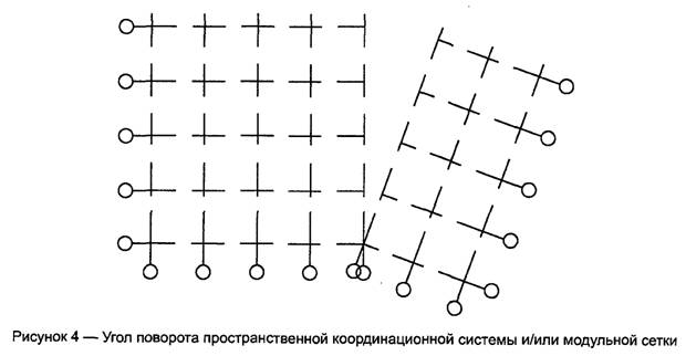
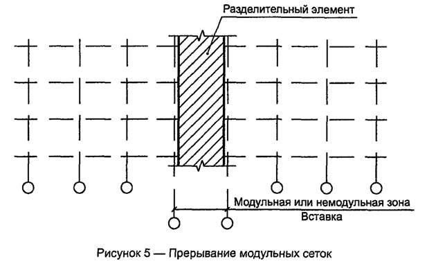
6 Coordination and design dimensions of building elements and equipment elements

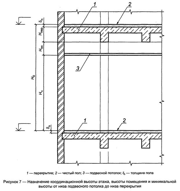


7 Binding of structural elements to coordination axes


(reference)Table of the main indicators of modular size coordination in construction